Supporting device and light exposure device

A technology of supporting device and moving parts, applied in photolithography process exposure device, microlithography exposure equipment, optics, etc., can solve the problems of performance error, unstable table position, unable to obtain positioning reproducibility, etc., to achieve a stable position Accuracy, effect of suppressing shape change

Active Publication Date: 2012-05-30
V TECH CO LTD
View PDF7 Cites 0 Cited by
  • Summary
  • Abstract
  • Description
  • Claims
  • Application Information

AI Technical Summary

Problems solved by technology

However, since the leaf spring is connected to the base, the movement of the table relative to the base is slight when moving in the Z-axis direction, but it also moves in the X-axis or Y-axis directions, and positioning reproducibility cannot be obtained. question
In response to this, a technology has been developed that uses an E-shaped leaf spring to reduce the movement of the table in the X-axis or Y-axis direction compared to its movement in the Z-axis direction. However, when the shape of the leaf spring changes greatly , there is an error in its performance and the problem of unstable workbench position

Method used


Image

  • Supporting device and light exposure device
  • Supporting device and light exposure device
  • Supporting device and light exposure device

Examples


Embodiment Construction

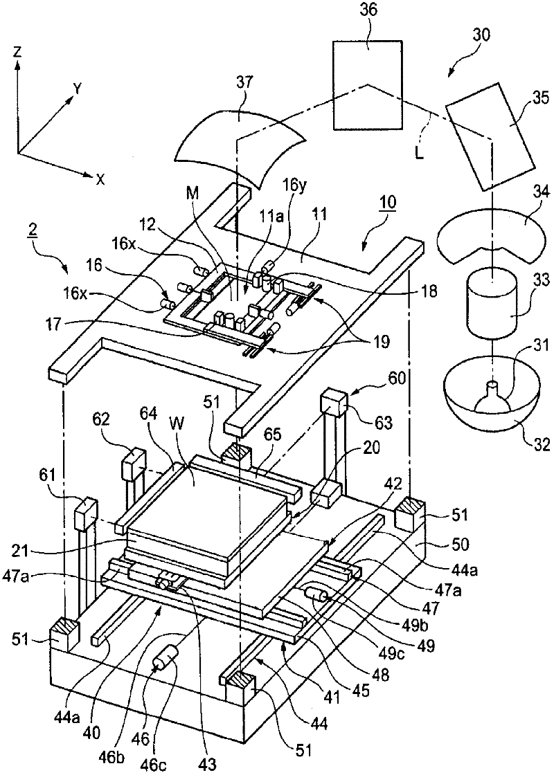
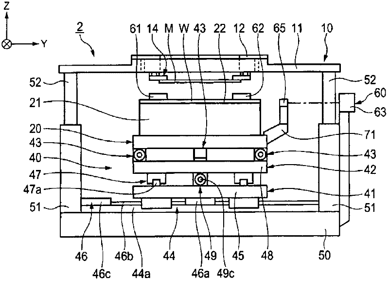
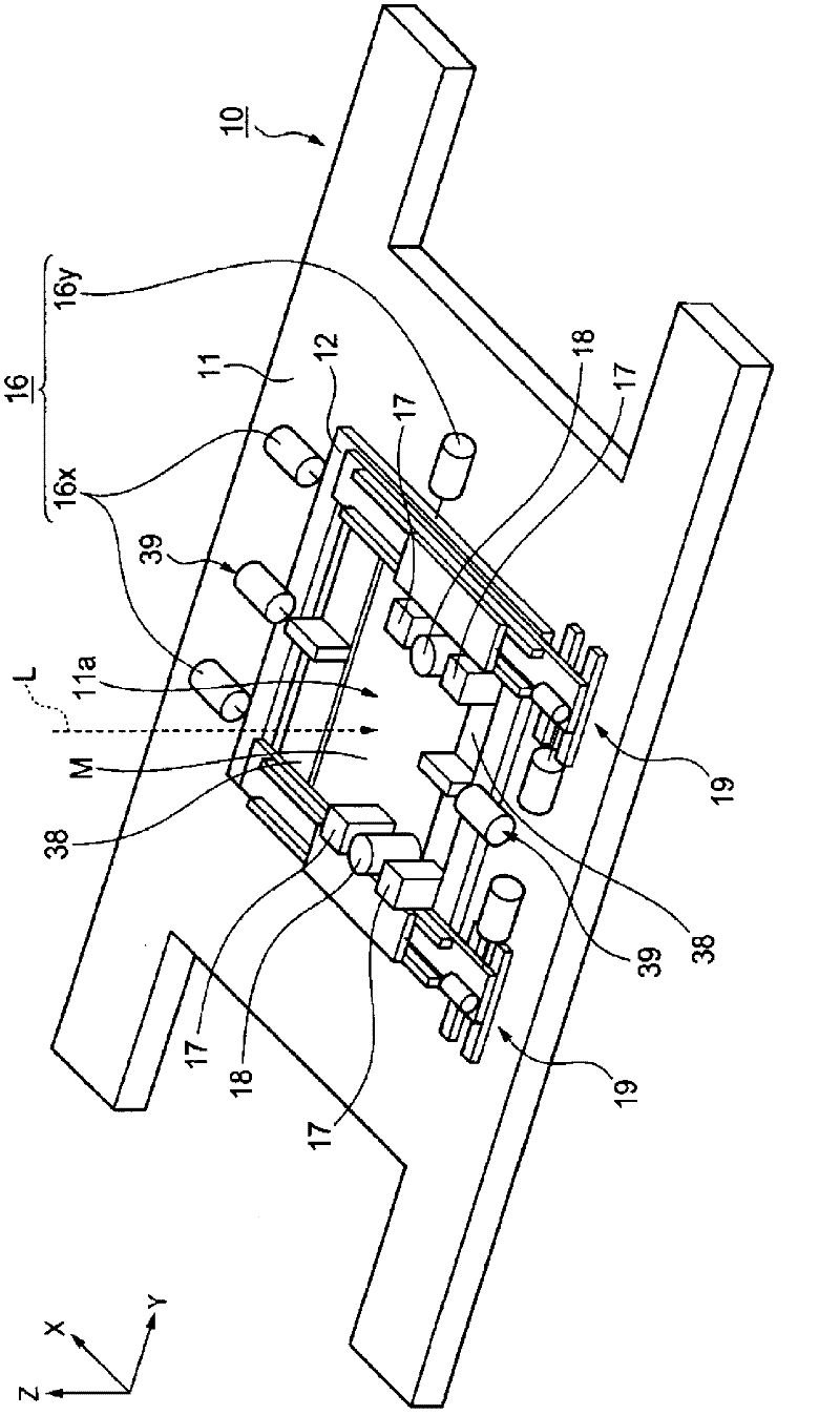
[0023] Next, an exposure unit using the support device according to the present invention will be described in detail with reference to the drawings. Here, let the Z-axis direction be the up-down direction, and let the X-axis direction and the Y-axis direction be the horizontal direction.

[0024] The exposure unit has: a first proximity exposure device body for exposing the first layer; a second proximity exposure device body for exposing the second layer; a third proximity exposure device body for exposing the third layer; and a body for exposing the fourth layer. The fourth is close to the main body of the exposure device. Here, the first to fourth proximity exposure apparatus main bodies only need to have different suction surfaces of the substrate holding parts described later, so only the first proximity exposure apparatus main body 2 will be described in detail below, and other descriptions will be given. Both are omitted.

[0025] Such as figure 1 As shown, the firs...


PUM


Abstract

Disclosed are a supporting device and a light exposure device, both of which can achieve the control of an angle of a stage with high repeatability. A spring member (450) is attached to the upper surface of an arm (439c) of a movable member (439) and the lower surface of a substrate support (442), so that the spring member (450), the arm (439c) and the substrate support (442) can move together in the Z-axis direction. In this manner, the change in the form of the spring member (450) can be prevented compared with a case where the spring member (450) is connected to a housing (431), and therefore the accurate positioning of a substrate stage (20) can be achieved stably regardless of the movement of the movable member (439).

Description

technical field [0001] The present invention relates to a support device and an exposure device for tilt adjustment of a movable table used in, for example, various manufactures and inspections. Background technique [0002] In semiconductor manufacturing processes and the like, interferometers are sometimes used to measure the flatness, parallelism, and thickness variation of semiconductor silicon wafers. Furthermore, in order to accurately measure the respective dimensions of the semiconductor silicon wafer to be measured, it is necessary to irradiate the detection light of the interferometer onto the surface of the measurement object at a predetermined angle with high accuracy. Therefore, a device for supporting a stage is used in order to tilt the measuring object with high precision. Patent Document 1 discloses a prior art support device for this purpose. The support device of Patent Document 1 performs arbitrary angle adjustment of the table by driving three points o...

Claims


Application Information

Patent Timeline
Patent Type & Authority Applications(China)
IPC IPC(8): H01L21/027G03F7/20
CPCG03F7/70716G03F7/7035
Inventor 池渊宏桐生恭孝户川悟
Owner V TECH CO LTD
Why Eureka
Try Eureka