
Lamination control device and lamination control method

A control device and control method technology, applied in the direction of harmonic reduction device, output power conversion device, high-efficiency power electronic conversion, etc., can solve the problems of grid harmonic pollution, grid pollution, waveform damage, etc., and improve the power factor of the grid , obvious cost advantage, simple and reliable circuit

Pending Publication Date: 2020-10-09
WUXI BEYOND AOK ELECTRIC
View PDF0 Cites 0 Cited by
  • Summary
  • Abstract
  • Description
  • Claims
  • Application Information

AI Technical Summary

Problems solved by technology

[0003] At present, one of the power adjustment methods of high-power heaters adopts non-stacked control devices; low-power heating loads have little impact on the power grid, and high-power loads will cause harmonic pollution or impact on the power grid
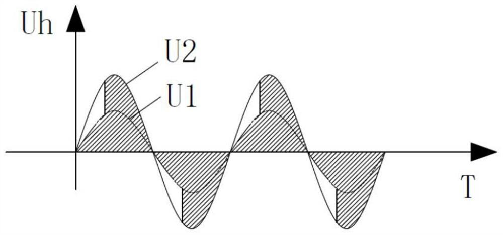
[0004] Because the traditional stack control scheme still adopts the conduction angle control method, the waveform is destroyed during the control process, so certain harmonics will be generated; figure 1 It is the current waveform diagram under the control of the conduction angle under the control of the lamination layer. The shaded part is the conduction part, and the blank part is the non-conduction part. It can be seen that the waveform has been damaged to varying degrees; resulting in different degrees of Harmonics cause pollution to the power grid. The most direct manifestation is that the power factor is lower than 0.9, which does not meet the electricity standard.

Method used

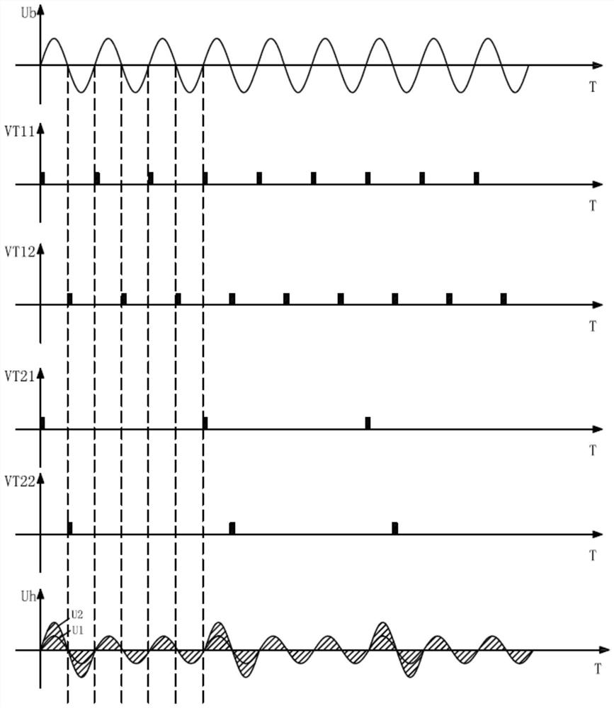

Image

  • Lamination control device and lamination control method
  • Lamination control device and lamination control method
  • Lamination control device and lamination control method

Examples


Embodiment Construction

[0038] The present invention will be further described below in conjunction with specific drawings and embodiments.

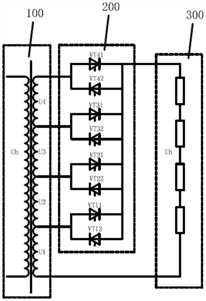
[0039] The embodiment of the present invention proposes a stack control device, such as figure 2 As shown, it includes: a controller, a transformer 100, and multiple sets of thyristors 200; in this embodiment, the electric heater 300 is used as a load; the stack control device needs to control the actual power of the electric heater 300 to meet different heating requirements; the controller is in figure 2 Not shown in the picture, hereby explain;

[0040] The transformer 100 includes a primary and a secondary, and the secondary of the transformer 100 is provided with a plurality of taps of different voltage levels and a reference terminal; figure 2 In the circuit, the secondary of the transformer 100 has taps of four different voltage levels, the voltage of each tap is U4>U3>U2>U1; the primary input voltage of the transformer 100 is Ub;

[0041] One end of...


PUM


Abstract

The invention provides a lamination control device. The lamination control device comprises a controller, a transformer and a plurality of groups of thyristors, wherein the transformer comprises a primary coil and a secondary coil; the secondary coil of the transformer is provided with a plurality of taps with different voltage levels and a reference end; one ends of each group of thyristors are correspondingly connected with the taps with different voltage levels and in the secondary coil of the transformer, and the other ends of each group of thyristors are connected with each other and connected with one end of a load; the reference end of the secondary coil of the transformer is connected with the other end of the load; each group of thyristors comprises a thyristor used for conductinga positive half cycle of the voltage of a corresponding tap and a thyristor used for conducting a negative half cycle of the voltage of the corresponding tap, and the two thyristor are connected in parallel in the group; and each thyristor is controlled by the controller. The invention further provides a lamination control method. The lamination control device and lamination control method of theinvention have the advantages of low current impact and almost no harmonic wave.

Description

technical field [0001] The invention relates to a power control device of a high-power heater, in particular to a lamination control device. Background technique [0002] When the high-power heater is in use, its power needs to be adjusted according to the usage requirements. [0003] At present, one of the power adjustment methods of high-power heaters adopts non-stacked control devices; low-power heating loads have little impact on the power grid, and high-power loads will cause harmonic pollution or impact on the power grid. [0004] Because the traditional stack control scheme still adopts the conduction angle control method, the waveform is destroyed during the control process, so certain harmonics will be generated; figure 1 It is the current waveform diagram under the control of the conduction angle under the control of the lamination layer. The shaded part is the conduction part, and the blank part is the non-conduction part. It can be seen that the waveform has bee...

Claims


Application Information

Patent Timeline
Patent Type & Authority Applications(China)
IPC IPC(8): H02J3/01H02J3/18H02M7/17H02M1/32
CPCH02J3/01H02J3/18H02M1/32H02M7/17H02M1/0058Y02B70/10Y02E40/30Y02E40/40
Inventor 何大庆林伯凝祁宇陶纹晶周方凯
Owner WUXI BEYOND AOK ELECTRIC
Learn More