Storage box

A storage box and storage slot technology, applied in the field of storage boxes, can solve problems such as few functions, and achieve the effects of convenient storage, prevention of bump damage, and good interchangeability

Pending Publication Date: 2020-10-09
SHANGHAI MOSHON TECH CO LTD
0 Cites 0 Cited by

AI-Extracted Technical Summary

Problems solved by technology

Existing storage boxes or storage bags usually only have a simple storage function, and a s...

Method used

Preferably, the bottom wall of the second chamber 210 is also provided with a heat dissipation hole 215, and the heat dissipation hole 215 can be a hollow structure such as a half-moon shape or a small hole shape, so that the pan-tilt camera 400 is placed in the second chamber 210 can dissipate heat better, especially during data transfer.
[0058] Preferably, the first slide bar 227 and the second slide bar 228 are provided with limiting components (not shown in the figure), such as limit springs, etc., clamping the mobile terminal on the first clamping plate 221 and the second clamping plate 222 500, the limit spring can apply tension to the first clamping plate 221 and the second clamping plate 222, so that the first clamping plate 221 and the second clamping plate 222 are clamped, so that the mobile terminal 500 can be clamped more stably. Resetting of the first fixed block 223 and the second fixed block 224 .
[0063] Preferably, as shown in FIG. 11 , a housing hole 236 is provided on the side wall of the third housing groove 233, and when the second data interface 231 is slidably received in the third housing groove 233, the second data interface The connector on 231 can be plugged into the accommodating hole 236 on the side wall of the third accommodat...

Abstract

The invention discloses a storage box. The storage box comprises a first shell and a second shell, wherein a first cavity is formed in the first shell, a second cavity is formed in the second shell, the first shell and the second shell are mutually buckled so that the first cavity and the second cavity can be communicated to form a closed accommodating cavity, the first equipment can be placed inthe accommodating cavity, a communication unit is arranged on the second shell, and the first equipment can be in communication connection with the second equipment through a communication unit on thesecond cavity. The storage box can protect a pan-tilt camera and prevent equipment from being damaged by collision, and the pan-tilt camera is convenient to store and carry; the functions of data connection and information transmission are achieved, connection between the mobile terminal and the pan-tilt camera is stable, and a port used for data connection is not prone to breakage; the storage box is convenient to operate and good in interchangeability, and can replace a proper connecting port according to actual use requirements so as to adapt to different mobile terminals.

Application Domain

Technology Topic

Image

  • Storage box
  • Storage box
  • Storage box

Examples

  • Experimental program(1)

Example Embodiment

[0045] In order to better understand the purpose, structure and function of the present invention, the storage box of the present invention will be described in further detail below with reference to the accompanying drawings.
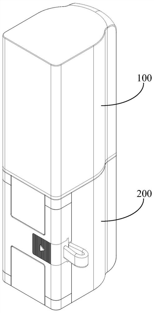
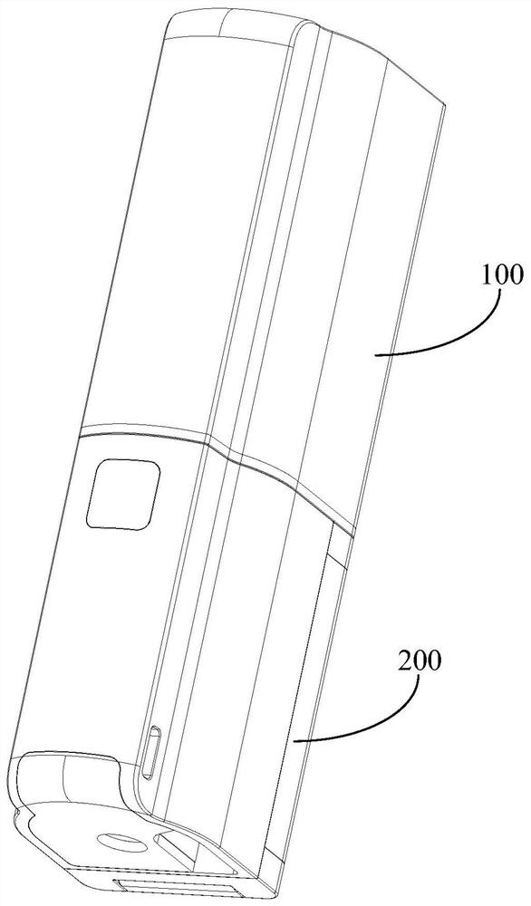
[0046] The storage box of the present invention is used to store the first device, and can realize the connection between the first device and the second device. The first device can be an electronic device such as a pan-tilt video camera, a camera, and a camera, and the second device can be a mobile phone, Pad and other mobile terminal equipment.
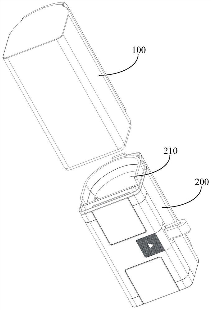
[0047] Specifically, the storage box includes a first shell and a second shell. A first chamber is formed inside the first shell, a second chamber is formed inside the second shell, and the first shell and the second shell The mutual buckling allows the first chamber and the second chamber to communicate and form a closed accommodating cavity, and the first device can be placed in the accommodating cavity.
[0048] At the same time, a fixing component is provided on the second casing, and the second device is connected to the second casing through the fixing component, so that the first device and the second device are simultaneously and stably connected to the second casing. Wherein, the fixing component may be a structure or fixing method capable of fixing a splint, a groove, a slot, or a tether, etc., with the purpose of stably connecting the second device to the second housing.
[0049] Further, a communication unit is provided on the second housing, and the first device can be communicatively connected with the second device through the communication unit on the second chamber. Wherein, the communication unit may be a data port directly connected with the first device or the second device, or may be a data connection component such as a data cable, a data connection plug, etc., or a wireless communication transmission method.
[0050] Such as Figure 1 to Figure 13 As shown, the storage box of this embodiment includes a first housing 100 and a second housing 200 that are buckled with each other. The first housing 100 is formed with a first chamber 110, and the second housing 200 is formed with a second housing. The cavity 210, the first cavity 110 and the second cavity 210 together form a closed accommodating cavity for accommodating a pan-tilt camera.
[0051] Specifically, such as Figure 1 to Figure 4 As shown, the first chamber 110 and the second chamber 210 in this embodiment are both long cylindrical, and the pan-tilt camera 400 can be directly placed in them. Of course, it can be understood that the specific size and shape of the first chamber and the second chamber can be flexibly set according to different models of the pan-tilt camera, and are not limited to those shown in the figure.
[0052] In order to facilitate the mutual buckling of the first housing 100 and the second housing 200, a positioning component and a locking component are provided at the connection of the first housing 100 and the second housing 200. The positioning component can be used to realize the first housing. The body 100 and the second housing 200 are precisely buckled, and the locking assembly can be used to realize the locking and fixing of the first housing 100 and the second housing 200. Among them, such as Image 6 with Picture 8 As shown, in this embodiment, the connecting end of the first housing 100 is provided with a positioning hole 111, a positioning groove 112, and a locking groove 113, and the connecting end of the second housing 200 is correspondingly provided with a positioning post 211, a positioning plate 212 and Locking claw 213.
[0053] Therefore, when the first housing 100 and the second housing 200 are buckled to each other, the positioning posts 211 and the positioning plate 212 on the second housing 200 are respectively inserted into the positioning holes 111 and the positioning holes on the first housing 100. In the groove 112, in order to realize the precise buckling of the first housing 100 and the second housing 200, the locking claw 213 on the second housing 200 is clamped in the locking groove 113 on the first housing 100 to The first housing 100 and the second housing 200 are locked and fixed.
[0054] Further, such as Figure 7 , Picture 10 with Picture 11 As shown, the side wall of the second housing 200 is provided with a first clamping plate 221 and a second clamping plate 222, wherein the first clamping plate 221 is horizontally arranged on the upper part of the second housing 200, and the second clamping plate 222 is horizontal. Located at the lower part of the second housing 200, the first clamping plate 221 and the second clamping plate 222 are arranged up and down opposite to each other, and a mobile terminal 500 such as a mobile phone or a Pad can be clamped between the first clamping plate 221 and the second clamping plate 222. Of course, it can be understood that the orientation words (such as upper, lower, level, etc.) in the embodiments are only for clearly describing structural features, and do not represent the orientation in actual life.
[0055] Specifically, a first fixing block 223 and a second fixing block 224 are respectively provided on both ends of the side wall of the second housing 200, wherein the first clamping plate 221 is hinged to the first fixing block 223, and the second clamping plate 222 is hinged to the first fixing block 223. On the two fixing blocks 224, the first clamping plate 221 can be rotated relative to the first fixing block 223, and the second clamping plate 222 can be rotated relative to the second fixing block 224 to switch the open or closed state of the first clamping plate 221 and the second clamping plate 222 , To realize the clamping of the mobile terminal 500.
[0056] Preferably, the second housing 200 is provided with a first accommodating groove 225 and a second accommodating groove 226, the first accommodating groove 225 is arranged close to the first fixing block 223, when the first clamping plate 221 is in the closed state, the first clamping plate 221 is received in the first receiving groove 225; similarly, the second receiving groove 226 is disposed close to the second fixing block 224, and when the second clamping plate 222 is in the closed state, the second clamping plate 222 is received in the second receiving groove 226. In this embodiment, when the first clamping plate 221 and the second clamping plate 222 are in the closed state, the surfaces of the first clamping plate 221 and the second clamping plate 222 and the side wall surface of the second housing 200 are located on the same plane, so that the second housing The overall appearance of the 200 is simple and beautiful.
[0057] Further, the first fixed block 223 is movably connected to the second housing 200 through the first sliding rod 227, and the second fixed block 224 is movably connected to the second housing 200 through the second sliding rod 228. The first sliding rod 227 can drive the second housing 200. A fixing block 223 moves upward relative to the side wall of the second housing 200, and the second sliding rod 228 can drive the second fixing block 224 to move downward relative to the side wall of the second housing 200. Thus, the first fixing block 223 and the second fixing block 224 can move with the first sliding rod 227 and the second sliding rod 228 to adjust the distance between the first clamping plate 221 and the second clamping plate 222, which facilitates different clamping sizes. 的mobile terminal 500. Of course, it is understandable that the position adjustment of the first clamping plate and the second clamping plate can also be realized by structures such as sliding rails and sliding grooves, which are not limited to those shown in the figure.
[0058] Preferably, the first sliding rod 227 and the second sliding rod 228 are provided with a limit component (not shown in the figure), such as a limit spring, etc., when the first clamping plate 221 and the second clamping plate 222 clamp the mobile terminal 500, The limit spring can exert a pulling force on the first clamping plate 221 and the second clamping plate 222, to promote the clamping of the first clamping plate 221 and the second clamping plate 222, so that the mobile terminal 500 can be clamped more stably, and it is also convenient for the first fixing block 223 and the second fixed block 224 reset.
[0059] Further, such as Picture 9 As shown, a first data interface 214 is provided on the bottom wall of the second chamber 210, and the first data interface 214 communicates with the following second data interface data through a connecting component (not shown) in the second housing 200 When the pan-tilt camera 400 is placed in the second chamber 210, the data interface on the pan-tilt camera 400 can be connected to the first data interface 214. Of course, it is understandable that the first data interface can also be arranged in other positions of the second chamber, as long as it is convenient to connect with the data interface of the pan-tilt camera.
[0060] Preferably, a heat dissipation hole 215 is further provided on the bottom wall of the second chamber 210. The heat dissipation hole 215 may be a hollow structure such as a half moon shape or a small hole shape, so that when the pan-tilt camera 400 is placed in the second chamber 210 It can better dissipate heat, especially during data transmission.
[0061] Further, such as Picture 10 with Picture 11 As shown, the second housing 200 is also provided with a second data interface 231. The second data interface 231 is in data communication with the connecting components in the second housing 200 through a soft data line 232. The data interface of the mobile terminal 500 can be connected to The second data interface 231 is connected, so that the communication connection between the mobile terminal 500 and the pan-tilt camera 400 is realized through the second data interface 231, the soft data line 232, the connecting component, and the first data interface 214. Among them, it should be noted that the connecting components in the second housing can adopt structural forms commonly used in the art, as long as they can realize the data connection between the first data interface and the second data interface, and will not be repeated.
[0062] In order to facilitate the connection with the mobile terminal 500, the second data interface 231 is provided separately from the second housing 200, and one end of the second data interface 231 is connected to the second housing 200 through a soft data cable 232. Among them, such as Picture 10 As shown, the second housing 200 is provided with a third receiving slot 233 for receiving the second data interface 231, the third receiving slot 233 is located between the first receiving slot 225 and the second receiving slot 226, the third receiving slot 233 A sliding groove 234 is provided on the inner wall of the second data interface 231, and a sliding rail 235 is correspondingly provided on the second data interface 231. The sliding rail 235 on the second data interface 231 can slide along the sliding groove 234 in the third receiving groove 233 to achieve alignment. 2. Storage of the data interface 231.
[0063] Preferably, such as Picture 11 As shown, the side wall of the third receiving groove 233 is provided with a receiving hole 236. When the second data interface 231 is slidably received in the third receiving groove 233, the connector on the second data interface 231 can be inserted into the In the accommodating hole 236 on the side wall of the three accommodating groove 233, the second data interface 231 can be accommodated better.
[0064] Optionally, such as Picture 12 As shown, the second data interface 231 includes an expansion joint 237 and a connection head 238. The expansion joint 237 is formed with a mounting groove, and the connection head 238 is detachably disposed in the installation groove in the expansion joint 237. Preferably, the installation groove A first magnetic attraction structure is provided, and a second magnetic attraction structure is provided on the connecting head 238. The first magnetic attraction structure and the second magnetic attraction structure are connected by magnetic attraction. Therefore, for different mobile terminals 500, a suitable connector 238 can be installed, such as USB, Type-C, Micro USB, etc.
[0065] Such as figure 1 with Figure 13 As shown, the use of the storage box of this embodiment is as follows: when the storage function is needed, the pan-tilt camera 400 is placed in the enclosed storage cavity formed by the first housing 100 and the second housing 200. , The first splint 221 and the second splint 222 are received in the first receiving groove 225 and the second receiving groove 226 on the second housing 200, and the second data interface 231 is received in the third receiving groove on the second housing 200 233 in.
[0066] When the data connection function needs to be used, the second data interface 231 is slid out from the third receiving slot 233 on the second housing 200, and a connector 238 that is compatible with the mobile terminal 500 is installed on the expansion joint 237; A clamping plate 221 and a second clamping plate 222 are rotated and opened from the first receiving groove 225 and the second receiving groove 226, and the distance between the first clamping plate 221 and the second clamping plate 222 is adjusted according to the size of the mobile terminal 500, so that the mobile terminal The 500 card is set between the first splint 221 and the second splint 222; the second data interface 231 is connected with the data interface of the mobile terminal 500; the pan-tilt camera 400 is placed in the second cavity inside the second housing 200 In the chamber 210, the data interface of the pan-tilt camera 400 is connected to the first data interface 214 in the second chamber 210.
[0067] Due to the soft texture of the soft data cable, the storage box of the present invention is used to connect the pan-tilt camera and the mobile terminal, which can prevent the device and the storage box from being damaged or destroyed when the device accidentally falls.
[0068] Such as Figure 14 to Figure 16 As shown, it is another embodiment of the second housing in the storage box of the present invention. In this embodiment, the second housing 300 is provided with a connection module 330. The connection module 330 includes a receiving connector 333 and a second data interface 331. The receiving connector 333 and the second data interface 331 pass through a soft data cable 332. Connected.
[0069] Correspondingly, a third data interface 334 is provided on the second housing 300, and the third data interface 334 is in data communication with the above-mentioned first data interface through the connecting components in the second housing 300, and the receiving connector of the connecting module 330 333 can be connected to the third data interface 334, and the data interface of the mobile terminal 500 can be connected to the second data interface 331. Thus, the communication connection between the mobile terminal 500 and the pan-tilt camera 400 is realized through the second data interface 331, the soft data line 332, the receiving connector 333, the third data interface 334, the connection component, and the first data interface.
[0070] Wherein, the receiving connector 333 of the connection module 330 and the third data interface 334 on the second housing 300 are detachably connected. In this embodiment, a plurality of connection modules 330 of different types are included. The form of the second data interface 331 in 330 is different, such as USB, Type-C, Micro USB, etc., to adapt to different types of mobile terminal 500 data interfaces.
[0071] Further, the second housing 300 is provided with a third receiving groove 335 for receiving the connection module 330, the third receiving groove 335 is located between the first receiving groove and the second receiving groove, and the inner wall of the third receiving groove 335 is provided There is a sliding groove 336, and the connecting module 330 is correspondingly provided with a sliding rail 337, and the sliding rail 337 on the connecting module 330 can slide along the sliding groove 336 in the third receiving groove 335 to realize the storage of the connecting module 330. Preferably, such as Figure 15 with Figure 16 As shown, the third data interface 334 is disposed in the third receiving groove 335, the receiving connector 333 of the connection module 330 is provided with a receiving hole 338, and the second data interface 331 can be inserted into the receiving hole 338 to Convenient storage.
[0072] Of course, it can be understood that the storage method of the connection module in this embodiment is not limited to the above method, and can be flexibly adjusted according to actual needs. For example, the second housing may be provided with a second housing for receiving the receiving connector. Three accommodating slots, a wire slot for accommodating the soft data cable, and a card slot for accommodating the second data interface, so as to separately accommodate the accommodating connector, the wire slot and the second data interface.
[0073] The use of the storage box of this embodiment is as follows: when the storage function is needed, the pan-tilt camera 400 is placed in the enclosed storage cavity formed by the first housing and the second housing. At this time, the first clamping plate and The second clamping plate is received in the first receiving groove and the second receiving groove on the second housing 300, and the connecting module 330 is received in the third receiving groove 335 on the second housing 300.
[0074] When the data connection function needs to be used, the second data interface 331 is taken out of the accommodating hole 338 on the accommodating connector 333, or the accommodating connector 333 of the connection module 330 adapted to the mobile terminal 500 is installed in the third accommodating In the slot 335 and connected with the third data interface 334; rotate the first clamping plate and the second clamping plate from the first accommodating groove and the second accommodating groove, and adjust the first clamping plate and the second clamping plate according to the size of the mobile terminal 500 The distance between the splints so that the mobile terminal 500 is clamped between the first splint and the second splint; the second data interface 331 is connected with the data interface of the mobile terminal 500; the pan-tilt camera 400 is placed in the second In the chamber, the data interface of the pan-tilt camera 400 is connected to the first data interface in the second chamber.
[0075] Therefore, the difference between the second housing in this embodiment and the second housing in the previous embodiment is that in the previous embodiment, the adaption to different mobile terminals is achieved by replacing the connector on the expansion joint. ,Such as Picture 12 As shown; in this embodiment, the connection module is replaced to achieve adaptation with different mobile terminals, such as Figure 15 Shown.
[0076] The storage box of the present invention has the following advantages: protect the pan-tilt camera, prevent the equipment from being damaged by bumps, and make the pan-tilt camera convenient to store and carry; it has the functions of data connection and information transmission, and the mobile terminal is connected with the pan-tilt camera Stable, the port used for data connection is not easy to be broken; the stability of the connection between the mobile terminal and the PTZ camera is strong, the device is not easy to fall, it is convenient to hold, and the portability is improved; it is easy to operate and has good interchangeability. Actual usage needs to replace suitable connection ports to adapt to different mobile terminals.
[0077] The present invention has been further described above with the help of specific embodiments, but it should be understood that the specific description here should not be construed as limiting the essence and scope of the present invention. Those of ordinary skill in the art will comment on the above after reading this specification. Various modifications made to the embodiments fall within the protection scope of the present invention.

PUM

no PUM

Description & Claims & Application Information

We can also present the details of the Description, Claims and Application information to help users get a comprehensive understanding of the technical details of the patent, such as background art, summary of invention, brief description of drawings, description of embodiments, and other original content. On the other hand, users can also determine the specific scope of protection of the technology through the list of claims; as well as understand the changes in the life cycle of the technology with the presentation of the patent timeline. Login to view more.

Similar technology patents

Roll type electrodialyzer

PendingCN114849477AEasy to carryAvoid bump damageGeneral water supply conservationElectrodialysisElectrodialysisStructural engineering
Owner:ZHEJIANG LVCHUANG BIOTECHNOLOGY CO LTD

Portable boiler wastewater component detection device

PendingCN114236070AAvoid bump damageEasy to grab and useTesting waterLinear motorElectric machine
Owner:刘杰

Classification and recommendation of technical efficacy words

  • Easy to store
  • Avoid bump damage

Shock absorber ankle exercise device

InactiveUS7892154B1Easy to storeEase of transportationSpace saving gamesMuscle exercising devicesMotion resistancePlantaris tendon
Owner:ALEXA AUSTEN

Portable high vegetable and fruit picking device

ActiveCN108076819AAvoid bump damagePicking devicesEngineeringPower output
Owner:HEXIAN LVYUAN VEGETABLE PLANTATION CO LTD

Lubricating oil-way of engine cylinder assembly

InactiveCN1786449AAvoid bump damageBeautiful structural designCylinder headsCylindersCylinder blockMotor oil
Owner:CHERY AUTOMOBILE CO LTD

Rainproof and sunshield multifunctional two-wheeled vehicle mobile phone holder

InactiveCN107813889AEnsure electricity safetyAvoid bump damageArticle supporting devicesOther supporting devicesElectrical and Electronics engineeringMobile phone
Owner:湖南海得利网络科技有限公司
Why Eureka
Try Eureka