Compression fixing device after cardiac pace-making operation and compression fixing method of compression fixing device

A fixation device and cardiac pacing technology, applied in the medical field, can solve the problems of inability to achieve hemostasis and compression, inaccurate positioning of the compression position, easy to change, etc., and achieve efficient hemostasis and compression, accurate positioning control, and convenient operation. Effect

Active Publication Date: 2020-10-13
河南弘辉医疗科技有限公司
View PDF7 Cites 2 Cited by
  • Summary
  • Abstract
  • Description
  • Claims
  • Application Information

AI Technical Summary

Problems solved by technology

The equipment and methods used for hemostasis in traditional postoperative care are relatively cumbersome. For example, the method of sandbag compression has brought great inconvenience to patients: the positioning of the pressurized position is not accurate and easy to change, and the pressurized sandbag is easy to fall off; The lying position can easily lead to decubitus ulcers. Generally, when you lie on the left side slightly, you need to raise your back, which is not very comfortable overall. The most important thing is that traditional compression methods generally use wearable clothing or bandages. However, due to the lack of stable support and pressure points during long-term use, it is easy to cause pressure changes to decrease, and the purpose of hemostasis and pressure cannot be achieved.

Method used


Image

  • Compression fixing device after cardiac pace-making operation and compression fixing method of compression fixing device
  • Compression fixing device after cardiac pace-making operation and compression fixing method of compression fixing device
  • Compression fixing device after cardiac pace-making operation and compression fixing method of compression fixing device

Examples


Embodiment Construction

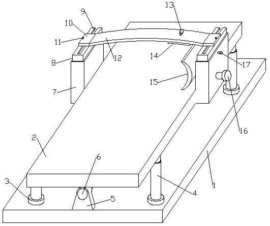
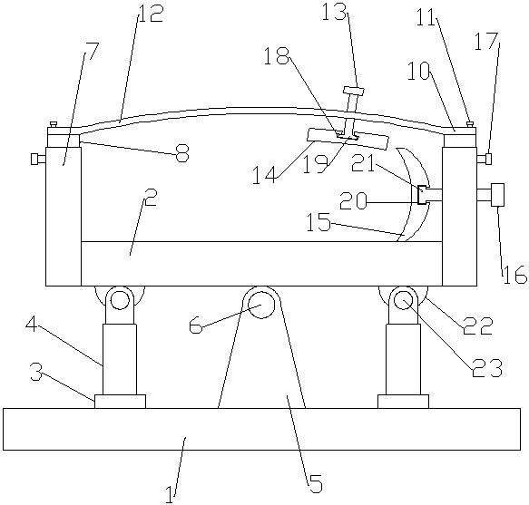
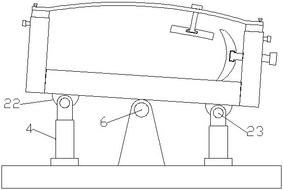
[0019] Such as figure 1 , 2As shown in , 3 and 4, a pressurization and fixing device after cardiac pacing includes a bottom support plate 1, and a fine-tuning plate 2 is installed on the top of the bottom support plate 1 through an electric push rod 4, and one end of the fine-tuning plate 2 is Both sides are fixedly equipped with longitudinal limit slots 7, and each vertical limit slot 7 is equipped with a lifting support 8 through a positioning bolt 17, and the top of each lifting support 8 is provided with a dovetail groove 9, each Sliders are installed movably in each of the dovetail slots 9, and a support slide 10 is fixedly installed on the top of each slide, and support plate fixing bolts 11 are installed on each support slide 10, and two support slides 10 are fixed. The chest limit adjustment bracket 12 is installed, and the upper surface of one end of the chest limit adjustment bracket 12 is provided with a pressurized bolt hole, and a pressurized bolt 13 is movably i...


PUM


Abstract

The present invention relates to a compression fixing device after a cardiac pace-making operation and a compression fixing method of the compression fixing device. A chest limiting adjustment bracketis fixedly arranged between two support sliding plates, an upper surface of one end of the chest limiting adjustment bracket is provided with a compression bolt hole, a compression bolt is movably arranged in the compression bolt hole, a bottom part of the compression bolt is connected with a compression plate arranged at a bottom part of the chest limiting adjustment bracket, a lateral positionlimiting plate is arranged at an inner side of a longitudinal limiting groove seat close to the compression plate, an outer end of the lateral position limiting plate is connected with a lateral position adjusting bolt positioned and arranged on the longitudinal limiting groove seat, a rotating shaft is fixedly arranged at a middle position of a bottom part of a fine adjustment plate, two ends ofthe rotating shaft are movably arranged in rotating shaft brackets, and bottom parts of the rotating shaft brackets are fixedly arranged on a bottom part supporting plate. When the device is used integrally, positioning of a pressurizing position is accurately controlled, a user is limited between the chest limiting adjustment bracket and the support sliding plates, and phenomena of falling, pressure changes, etc. do not occur by utilizing a bolt compression structure.

Description

technical field [0001] The invention relates to the medical field, in particular to a pressurization fixation device and a pressurization fixation method after cardiac pacing. Background technique [0002] Cardiac pacemaker implantation refers to the artificial implantation of a cardiac pacemaker, which uses a pulse current of a specific frequency to stimulate the heart through wires and electrodes, replacing the pacemaker point of the heart to drive the heart to beat. A safe and effective method for cardiac conduction dysfunction, especially for the treatment of severe chronic arrhythmias. Cardiac pacemaker is an electronic therapy device implanted in the body. It sends out electric pulses powered by batteries through a pulse generator, and through the conduction of wire electrodes, it stimulates the myocardium in contact with the electrodes, making the heart excited and contracted, so as to achieve therapeutic effect. For the purpose of cardiac dysfunction due to certain ...

Claims


Application Information

Patent Timeline
Patent Type & Authority Applications(China)
IPC IPC(8): A61B17/12A61B90/14A61G7/057
CPCA61B17/12A61B2017/12004A61G7/057A61B90/14
Inventor 王登峰
Owner 河南弘辉医疗科技有限公司
Why Eureka
Try Eureka