Automatic electrostatic spraying equipment for multiple groups of horizontal rod workpieces

An electrostatic spraying, horizontal rod technology, applied in liquid spraying equipment, electrostatic spraying devices, spraying devices, etc., can solve the problems of high cost, spending a lot of time manually adjusting electrostatic spray guns, low efficiency, etc., to reduce costs and operation. cost, meet the needs of large-scale production, and improve the effect of production efficiency

Pending Publication Date: 2020-10-13
WEIFANG EAST PIPE IND TECHNICAL CO LTD +1
1 Cites 0 Cited by

AI-Extracted Technical Summary

Problems solved by technology

[0004] 1. Set up 2 or more electrostatic spray guns to spray only one round tube, which is inefficient;
[0005] 2. A single round tube requires two or more electrostatic spray guns for spraying, the cost of equipment is high, and the energy consumption of equipment operation is also high;
[0006] 3. It is only suitable for spraying a small number of circular tubes. Once the specifications of the circular tubes are not suitable, it will ...

Method used

Described upper automatic spray gun group 5 and lower automatic spray gun group 6 all comprise the spray guns that a plurality of equal intervals are arranged, and spray gun is correspondingly set up and down; Described upper automatic spray gun group 5 and lower automatic spray gun group 6 outsides are respectively provided with positive pressure The protective cover 7 and the positive pressure protective cover 7 are made of non-stick powder PP material, and the color change speed is fast. Input compressed air into the cavity of the positive pressure protective cover 7 to prevent the cavity from entering the powder and prolong the life of the spray gun Effect.
Many groups of rod class workpieces 9 are delivered to the spraying area of ​​spray booth 1 horizontally, and the upper and lower directions of multiple groups of rod class workpieces 9 are respectively equipped with a set of automatic spray gun groups, and the automatic spray gun groups are connected to the horizontal mobile frame 2, and the horizontal The moving frame 2 drives the automatic spray gun group to perform horizontal reciprocating motion along the vertical direction of the rod workpiece 9, and a single spray gun can spray a plurality of rod workpieces 9 in the reciprocating stroke; the height of the middle frame 23 can be adjusted vertically, and then Adjust the height of the upper automatic spray gun group 5, and realize the automatic expansion and contraction of the telescopic cylinder 813 inwards or outwards through hydraulic pressure, so that the distance between adjacent supporting wheels 86 can be reduced or increased, which can meet the needs of rod workpieces of different sizes. 9 spraying; the air knife cleaning system 15 installed on the side of the spray booth 1 can automatically clean the powder attached to the upper surface of the V-shaped bottom plate 13, eliminating the need for manual cleaning, and the equipment can change colors faster; the powder at the bottom of the inner cavity of the spray booth 1 The recovery system recovers the unadsorbed and oversprayed powder to realize the recycling of the powder; the smoke system on the upper part of the inner cavity of the spray booth 1 absorbs and purifies the smoke generated during the powder thermosetting process to reduce environmental pollution; the V-shaped bottom plate 13 and the inverted V-shaped top plate 10 have obvious diver...

Abstract

The invention discloses an automatic electrostatic spraying equipment for multiple groups of horizontal rod workpieces. The automatic electrostatic spraying equipment comprises a spraying room, the spraying room is installed at the position perpendicular to the conveying direction of the rod type workpieces, and the rod type workpieces are horizontally conveyed through a conveying device; the conveying device comprises a hollow rotating shaft, and the outer portion of a main body of the hollow rotating shaft is sleeved with riding wheels and telescopic assemblies which are alternately arranged; a horizontal moving frame of an E-shaped structure is installed in the spraying room, the horizontal moving frame drives an automatic spraying gun set to do horizontal reciprocating motion in the vertical direction of the rod type workpiece, and the automatic spraying gun set comprises an upper automatic spraying gun set and a lower automatic spraying gun set. The automatic spraying device can automatically spray multiple sets of rod workpieces, the large-scale production requirement is met, and the production efficiency is greatly improved; the applicability of the equipment can be improved, and horizontal automatic spraying of rod workpieces of various specifications is achieved; a single spray gun can spray multiple sets of rod workpieces, and the equipment cost and the operation costare reduced.

Application Domain

Liquid spraying plants

Technology Topic

Image

  • Automatic electrostatic spraying equipment for multiple groups of horizontal rod workpieces
  • Automatic electrostatic spraying equipment for multiple groups of horizontal rod workpieces
  • Automatic electrostatic spraying equipment for multiple groups of horizontal rod workpieces

Examples

  • Experimental program(1)

Example Embodiment

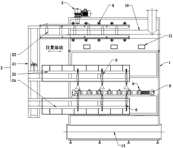
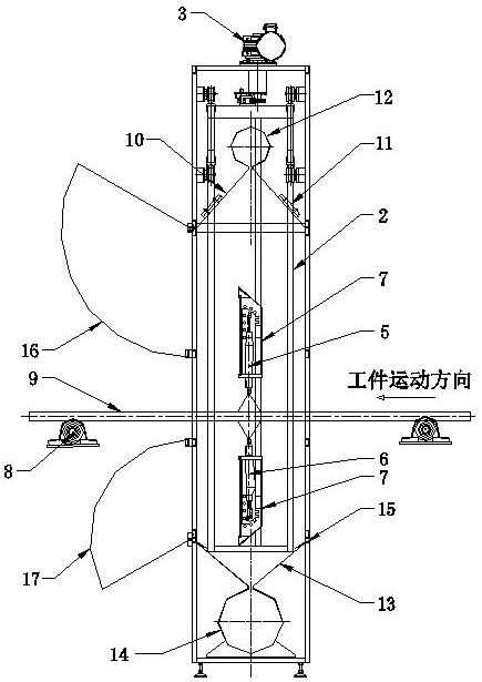
[0032] In order to have a clearer understanding of the technical features, objectives and effects of the present invention, specific embodiments of the present invention will now be described with reference to the accompanying drawings.
[0033] Such as figure 1 with figure 2 As shown in common, the present invention provides an automatic electrostatic spraying equipment for multiple groups of horizontal rod type workpieces, including spray booth 1, horizontal moving frame 2, automatic spray gun group, conveying device 8, air knife cleaning system 15, powder recovery system and smoking system.
[0034] As the main body of the equipment, the spray booth 1 is installed in the vertical position of the conveying direction of the rod-like workpieces 9. The rod-like workpieces 9 are conveyed horizontally by the conveying device 8. The rod-like workpieces 9 can also be rotated through cooperation with the rotating device during conveying. , The rod-type workpiece 9 can be rotated or not, and the spraying effect is better when rotating; the conveying device 8 can simultaneously send 2-1000 rod-type workpieces 9 to the spraying area in the spray booth 1 for spraying, the rod-type workpiece 9 is round tube, round rod, square tube, profile and other types.
[0035] Such as image 3 , Figure 4 , Figure 5 with Image 6 As shown together, the conveying device 8 includes a hollow shaft 81. One end of the hollow shaft 81 is provided with a solid shaft head 83, and the other end is provided with a hollow shaft head 84. The solid shaft head 83 and the hollow shaft head 84 rotate with the bearing seat 85 respectively. Connection; The solid shaft head 83 is connected to the motor.
[0036] The cross section of the hollow shaft 81 is a square structure, and the four sides are smoothly transitioned. The main body of the hollow shaft 81 is provided with a strip-shaped sliding hole 82 in the axial direction. The length of the strip-shaped sliding hole 82 is less than the length of the hollow shaft 81; The main body of the rotating shaft 81 is sheathed with alternately arranged supporting wheels 86 and telescopic components 87. The supporting wheels 86 are used to support rod-like workpieces 9. The rotation of the hollow shaft 81 realizes the synchronous rotation of the supporting wheels 86 and the telescopic components 87. The telescopic components 87 is used to adjust the distance between adjacent supporting wheels 86 to suit the spraying of rod-like workpieces 9 of different pipe diameters.
[0037] The telescopic assembly 87 includes an inner cylinder 88 and an outer cylinder 810 nested in each other. A hydraulic oil chamber 812 is provided between the inner cylinder 88 and the outer cylinder 810. Both ends of the inner cylinder 88 and the outer cylinder 810 Telescopic cylinders 813 are respectively installed in the parts, and the telescopic cylinders 813 expand and contract under the action of hydraulic pressure.
[0038] The inner cylinder 88 is provided with an outer shoulder 89 on the outside of the end close to the solid shaft head 83; the outer cylinder 810 is provided with an inner shoulder 811 on the inside of the end close to the solid shaft 83; the telescopic cylinder 813 Two ring-shaped protrusions 814 are respectively provided on the inner and outer walls of one end. The two ring-shaped protrusions 814 on the inner wall are in sliding fit with the outer wall of the inner cylinder 88. A first ring is provided between the two ring-shaped protrusions 814. Sealing ring 815; two annular protrusions 814 on the outer wall are in sliding fit with the inner wall of the outer cylinder 810, a second sealing ring 816 is arranged between the two annular protrusions 814; a first sealing ring 815 and a second sealing The ring 816 cooperates for sealing the hydraulic oil cavity 812.
[0039] An end of the inner cylinder 88 close to the hollow shaft 81 is provided with an inner baffle plate 818, and an end of the outer cylinder 810 close to the hollow shaft 81 is provided with an outer baffle plate 817; the inner baffle plate 818 and the outer baffle plate 817 cooperate to make the telescopic cylinder 813 performs position limit to prevent it from slipping out.
[0040] A push plate 819 is respectively installed on the outer end surface of the telescopic cylinder 813, and the push plate 819 abuts against the wall surfaces on both sides of the supporting wheel 86.
[0041] The inner cylinder 88 is fixed with a vertically arranged and cylindrical sliding member 820. The sliding member 820 can slide in the strip-shaped sliding hole 82 of the hollow shaft 81. The sliding member 820 plays a role in the sliding of the inner cylinder 88. To the positioning function; the sliding member 820 is installed inside the oil nozzle 821, one end of the oil nozzle 821 is connected to the hydraulic oil chamber 812, the other end of the oil nozzle 821 is connected to the hydraulic oil pipe 822, the hydraulic oil pipe 822 penetrates the hollow shaft 81 and the hollow shaft Inside 81, the hydraulic oil pipe 822 also needs to use a rotary joint during the connection process to avoid the problem of winding of the hydraulic oil pipe 822 during the rotation.
[0042] The two ends of the hollow shaft 81 are provided with a first stop plate 824 and a second stop plate 825. The first stop plate 824 and the second stop plate 825 perform an arrangement on the two ends of the supporting wheel 86 and the telescopic assembly 87 alternately arranged in the middle. Limit; One side of the second stop plate 825 is provided with a return spring 823, the return spring 823 is sleeved on the main body of the hollow shaft 81, and the return spring 823 is used to always maintain the compression between the supporting wheel 86 and the telescopic assembly 87 force.
[0043] The present invention uses hydraulic pressure to realize the inward or outward automatic expansion and contraction of the inner telescopic cylinder 813 at both ends of the inner cylinder 88 and the outer cylinder 810, and the telescopic cylinder 813 retracts inward to make the distance between the adjacent supporting wheels 86 The shrinking is performed, and the telescopic cylinder 813 extends outwards to increase the distance between the adjacent supporting wheels 86, so as to adapt to the spraying of rod-like workpieces 9 of different pipe diameters.
[0044] Such as figure 1 with figure 2 As shown together, a horizontally reciprocating horizontally movable frame 2 is installed in the spray booth 1. The horizontally movable frame 2 has an E-shaped structure, which occupies a small space; the horizontally movable frame 2 consists of a side frame 21 and a top frame 22. The middle frame 23 and the bottom frame 24 are composed, and the height of the middle frame 23 can be adjusted vertically to adapt to the spraying of the rod-like workpieces 9 of different pipe diameters.
[0045] The reciprocating motion of the horizontal moving frame 2 provides a power source through a driving device 3. The driving device 3 is installed on the top of the spray booth 1, which can reduce powder pollution and facilitate maintenance; the gears installed on the output shaft of the driving device 3 are installed on the top of the top frame 22 The racks of the top frame 22 are engaged; the top and bottom of the top frame 22 are respectively connected to the guide roller 4 in rolling connection, the guide roller 4 is fixed on the inner wall of the spray booth 1, and the guide roller 4 supports and guides the movement of the top frame 22 ; The driving device 3 drives the top frame 22 to move in the process to realize the overall movement of the horizontal moving frame 2.
[0046] The horizontal moving frame 2 drives the automatic spray gun group to reciprocate horizontally along the vertical direction of the rod-like workpiece 9. The automatic spray gun group includes the upper automatic spray gun group 5 and the lower automatic spray gun group 6, the upper automatic spray gun group 5 and the lower automatic spray gun group 6 They are respectively located at the upper and lower positions of the rod-like workpieces 9, and spray the rod-like workpieces 9 from the upper and lower directions at the same time; the upper automatic spray gun group 5 is fixed on the middle frame 23 of the horizontal moving frame 2, and the lower automatic spray gun group 6 is fixed on Move the frame 2 horizontally on the bottom frame 24.
[0047] The upper automatic spray gun group 5 and the lower automatic spray gun group 6 both include a plurality of spray guns arranged at equal intervals, and the spray guns are arranged correspondingly up and down; the upper automatic spray gun group 5 and the lower automatic spray gun group 6 are respectively provided with a positive pressure protective cover 7 , The positive pressure protective cover 7 is made of non-stick powder PP material, and the color change speed is fast. Compressed air is input into the cavity of the positive pressure protective cover 7 to prevent powder from entering the cavity, which has the effect of extending the life of the spray gun.
[0048] The bottom of the inner cavity of the spray booth 1 is equipped with a powder recovery system. The powder recovery system includes a V-shaped bottom plate 13. The inclination angle of the V-shaped bottom plate 13 is greater than the angle of repose of the powder. The bottom of the V-shaped bottom plate 13 is connected to the horizontal recovery pipe 14 Connected, the unadsorbed and oversprayed powder can slide down to the recovery pipe 14 by itself to realize the recycling of the powder.
[0049] An air knife cleaning system 15 is provided on the side of the spray booth 1, and the air knife cleaning system 15 is used to clean the powder attached to the V-shaped bottom plate 13.
[0050] The upper part of the inner cavity of the spray booth 1 is provided with a smoking system. The smoking system includes an inverted V-shaped top plate 10, which can collect the smoke generated when the powder is thermoset. The upper part of the inverted V-shaped top plate 10 and a smoking pipe 12 Connected; the smoking system purifies the flue gas and reduces environmental pollution.
[0051] The bottom of the inverted V-shaped top plate 10 is provided with a lighting lamp 11, and the brightness of the lighting lamp 11 is greater than 600 lumens, which is convenient to observe the spraying effect.
[0052] The exit of the spray booth 1 is provided with an upper opening door 16 and a lower opening door 17, which is convenient for maintenance.
[0053] The specific working principle of the present invention:
[0054] Multiple groups of rod type workpieces 9 are transported horizontally to the spraying area of ​​spray booth 1, and a set of automatic spray gun groups are arranged in the upper and lower directions of the multiple groups of rod type workpieces 9 respectively. The automatic spray gun groups are connected to the horizontal moving frame 2 and the horizontal moving frame 2 The automatic spray gun group is driven to reciprocate horizontally along the vertical direction of the rod type workpiece 9. A single spray gun can spray multiple rod type workpieces 9 in the reciprocating stroke; the height of the middle frame 23 can be adjusted vertically, and then the automatic adjustment The height of the spray gun group 5 can realize the automatic expansion and contraction of the telescopic cylinder 813 inward or outward through hydraulic pressure, so that the distance between adjacent supporting wheels 86 can be reduced or increased, which can meet the requirements of spraying rod-like workpieces 9 of different sizes. The air knife cleaning system 15 on the side of the spray booth 1 can automatically clean the powder attached to the upper surface of the V-shaped bottom plate 13, eliminating manual cleaning, and the equipment changes color faster; the powder recovery system at the bottom of the inner cavity of the spray booth 1, Recycle the unadsorbed and oversprayed powder to realize the recycling of the powder; the smoking system on the upper part of the inner cavity of the spray booth 1 absorbs and purifies the flue gas generated during the powder thermosetting process to reduce environmental pollution; V-shaped bottom plate 13 and inverted The V-shaped top plate 10 has obvious diversion effect, so that the powder and smoke in the spray booth 1 can be collected more fully.
[0055] The above are examples of the best embodiments of the present invention, and the parts that are not mentioned in detail are the common knowledge of those of ordinary skill in the art. The protection scope of the present invention is subject to the content of the claims, and any equivalent transformation based on the technical enlightenment of the present invention is also within the protection scope of the present invention.

PUM

no PUM

Description & Claims & Application Information

We can also present the details of the Description, Claims and Application information to help users get a comprehensive understanding of the technical details of the patent, such as background art, summary of invention, brief description of drawings, description of embodiments, and other original content. On the other hand, users can also determine the specific scope of protection of the technology through the list of claims; as well as understand the changes in the life cycle of the technology with the presentation of the patent timeline. Login to view more.

Similar technology patents

Ultrasonic tin plating device and tin plating method

PendingCN113186478AMeet the needs of mass productionSolve environmental problemsHot-dipping/immersion processesMetallurgyTin plating
Owner:常州井芯半导体设备有限公司

Metal and glass packaging sintering furnace

ActiveCN110243186AUse time wiselyMeet the needs of mass productionMaintainance of heating chambersFurnace coolingUse of timeTelescopic cylinder
Owner:BENGBU XINGCHUANG ELECTRONICS TECH CO LTD

Vertical packaging structure with upper cup and lower cup

PendingCN114005820AMeet the integrationMeet the needs of mass productionSolid-state devicesSemiconductor devicesElectrical connectionHemt circuits
Owner:深圳市唯亮光电科技有限公司

Classification and recommendation of technical efficacy words

  • Meet the needs of mass production
  • Increase productivity

Automatic automobile shifting fork machining machine tool

InactiveCN103920918ARealize automatic processingMeet the needs of mass productionMilling equipment detailsMetal working apparatusBatch productionEngineering
Owner:珠海市金蓝五金机电设备有限公司

Turnover mechanism used for transmission line

ActiveCN103681422ASatisfy flip action requirementsMeet the needs of mass productionSemiconductor/solid-state device manufacturingConveyor partsTransmission lineEngineering
Owner:BEIJING NAURA MICROELECTRONICS EQUIP CO LTD

Multi-lens image photographing module

InactiveCN104836940ATroubleshoot difficult correctionsMeet the needs of mass productionTelevision system detailsColor television detailsCamera lensImage synthesis
Owner:SUYIN OPTRONICS

Injection molding part sprue shearing method

PendingCN113635525AImprove work efficiencyMeet the needs of mass productionBatch productionEngineering
Owner:SUZHOU LICHUANG PRECISION MOLD TECH CO LTD

Method and system to define implement and enforce workflow of a mobile workforce

ActiveUS20130090969A1Improves work force capabilityIncrease productivityResourcesWorkflow processWorkflow
Owner:HYPHEN SOLUTIONS LLC

Apparati, methods, and compositions for universal microbial diagnosis, detection, quantification, and specimen-targeted therapy

InactiveUS20120129794A1Increase productivityAccurate and rapid and sensitive microbial diagnosis and detection and quantificationAntibacterial agentsBiocidePopulationMolecular Targeted Therapies
Owner:DOWD SCOT E +2
Why Eureka
Try Eureka