Rotary touch obstacle meeting mechanism, power integration mechanism and clothes drying machine

A technology of rotating contact and encountering resistance, which is applied in the direction of clockwork mechanism, washing device, textile and paper making, etc. It can solve the problems of large size, easy impact of drying rod on user's head, and inability to control the suspension of drying rod in the first place. , to achieve the effect of reducing the overall volume, improving accuracy and timeliness

Pending Publication Date: 2020-10-13
GUANGDONG HOTATA TECH GRP
View PDF0 Cites 4 Cited by
  • Summary
  • Abstract
  • Description
  • Claims
  • Application Information

AI Technical Summary

Problems solved by technology

[0002] At present, because the smart clothes dryer can realize lifting, drying, disinfection and other functions, the smart clothes dryer is gradually accepted by the majority of users and widely used in every household; but because the clothes dryer can drive the drying rod to move up and down, If the user stands under the clothes dryer, the lowered drying rod will easily hit the user's head, which poses a certain safety hazard
[0003] In order to solve the above-mentioned safety problems, the clothes dryers on the market are equipped with a blocking mechanism, which can detect whether there is any collision with other objects during the lowering process of the drying rod. However, the existing blocking mechanisms generally use a combination of sensors and springs. way to detect the state of the winding assembly; however, since the spring has a certain range of expansion and contraction, the volume of the resistance mechanism that uses the sensor and the spring to cooperate with each other is relatively large
[0004] And the existing blocking mechanism is generally installed on the winding assembly, by indirectly detecting the rotating shaft on the winding assembly or the motion state of the slide block linked with the steel wire to judge whether the current drying rod is blocked; When the airing rod encounters obstacles during the lifting process, the first thing to change directly and first must be the tightness of the steel wire. However, if the motion state of the rotating shaft or slider is detected according to the above, the accuracy and timeliness of the detection will be relatively poor , it is impossible to control the suspension of the drying pole immediately, and there are still potential safety hazards
[0005] In addition, some resistance mechanisms cannot detect whether the current steel wire is in a slack state, so that the wire winding assembly needs to tighten the steel wire before it can drive the drying rod to move up and down when it is just started, so that the movement of the drying rod has a certain delay , making the user experience poor

Method used


Image

  • Rotary touch obstacle meeting mechanism, power integration mechanism and clothes drying machine
  • Rotary touch obstacle meeting mechanism, power integration mechanism and clothes drying machine
  • Rotary touch obstacle meeting mechanism, power integration mechanism and clothes drying machine

Examples


Embodiment 1

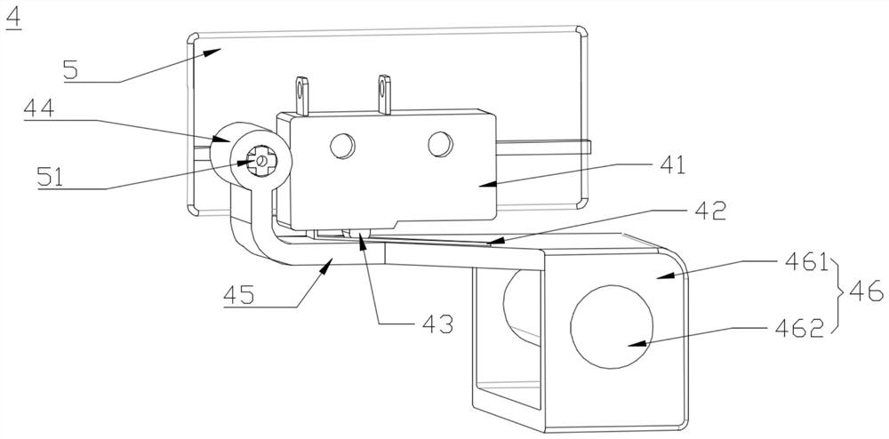
[0046] This embodiment provides a rotary touch resistance mechanism 4, which uses the switch shrapnel 42 instead of the traditional spring to realize the reset function, and the overall size of the resistance mechanism 4 can be further reduced through the bending structure of the pressing part and the effect of rotation resistance. volume.

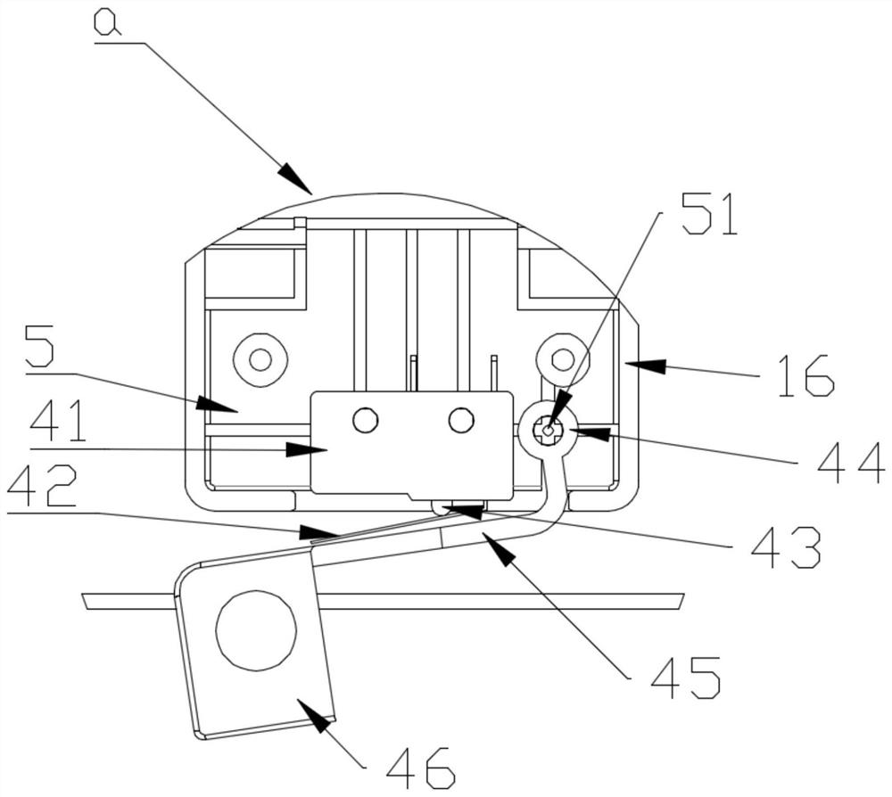
[0047] Such as figure 1 As shown, the rotary touch resistance mechanism 4 in this embodiment includes a cover plate 5, and the cover plate 5 is used as a carrier so that both the pressing member and the main body member 41 can be arranged on the cover plate 5 to limit the resistance. The positional relationship between the pressing piece and the main piece 41.

[0048]The body part 41 is fixed on the cover plate 5, and any side wall of the body part 41 is provided with a switch elastic piece 42. The switch elastic piece 42 has a certain elasticity relative to the body part 41. Elastic deformation can occur. The switch elastic piece 42 c...

Embodiment 2

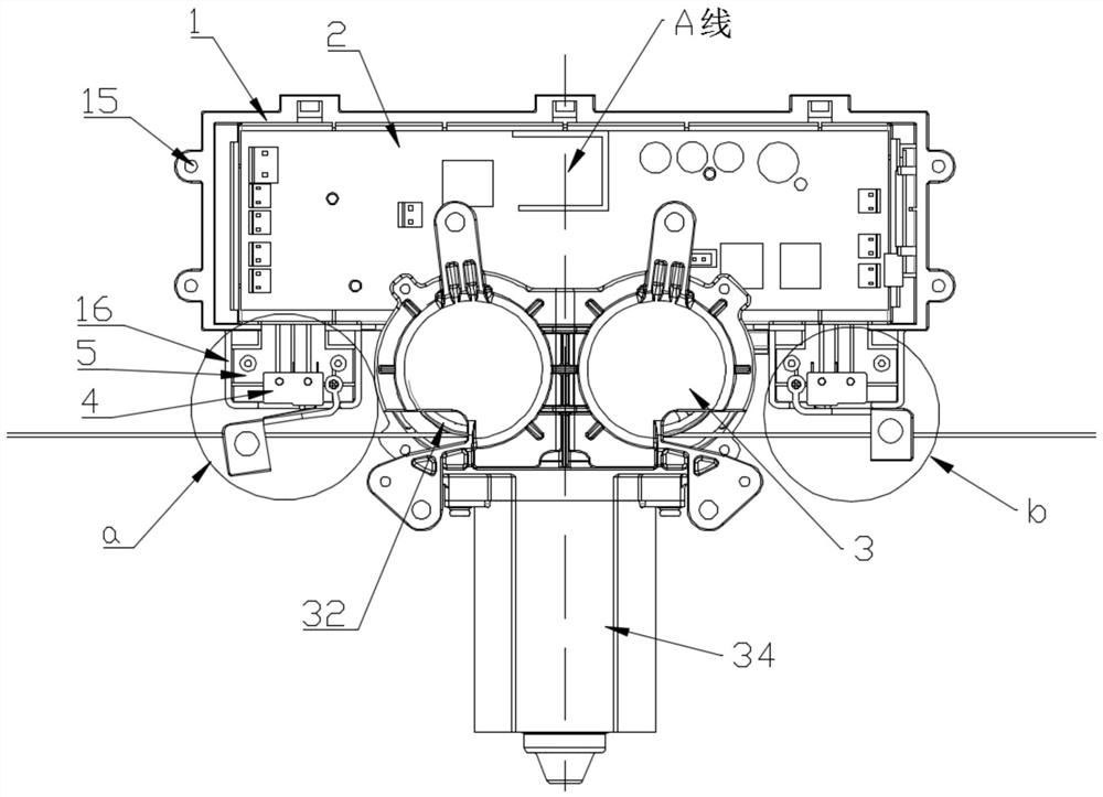
[0059] This embodiment provides a power integration module, which integrates the main control board 2, the resistance mechanism 4 and the winding device 3 in the first embodiment on a box body 1, so that the power integration module is small in size and compact in structure, making The internal wiring is neat and orderly, which can speed up the efficiency of disassembly and assembly while eliminating potential safety hazards, and improve the internal aesthetics.

[0060] Such as Figure 2-7 As shown, the power integration module of this embodiment includes a box body 1 , a main control board 2 mounted on the box body 1 , a winding device 3 and the resistance mechanism 4 in the first embodiment. Wherein the box body 1 includes a bottom plate 11 and a surrounding plate 12, the surrounding plate 12 is vertically connected to the edge of the bottom plate 11, so that the two jointly define an accommodation space, which can be used to accommodate the main control board 2 and other ...

Embodiment 3

[0073] This embodiment provides a clothes dryer, including a clothes dryer host and a power integration module as described in Embodiment 2; Figure 8 As shown, the host is provided with a bottom panel 6, and the box body 1 is reversely installed on the bottom panel 6, so that the bottom panel 6 blocks the accommodating space. At the same time, in order to install the box body 1 on the bottom panel 6 of the main body of the washing machine, at least one side wall fixing hole 15 extending outward is provided on each of the short side walls 121, and the The side wall fixing hole 15 is not in contact with the bottom plate 11, that is, the side wall fixing hole 15 can be arranged on the upper edge of the short side wall 121, or in the middle of the short side wall 121, but always Keep a certain distance from the bottom plate 11, so that when the box body 1 is installed on the bottom panel 6 of the clothes dryer, the accommodating space is facing the bottom panel 6 of the clothes d...


PUM


Abstract

The invention discloses a rotary touch obstacle meeting mechanism, a power integration mechanism and a clothes drying machine. The obstacle meeting mechanism comprises a cover plate, a body part, an on-off elastic sheet and an abutting part. The cover plate is provided with a rotating shaft. The body part is arranged on the cover plate and is provided with a side wall. The on-off elastic sheet isconnected with the side wall and is provided with a contact portion in electric wire connection with the body part within the deformation range of the on-off elastic sheet. The abutting part comprisesa rotating portion, an abutting portion and a wire pressing portion, all of which are connected in sequence, the rotating portion is in pivotal joint with the rotating shaft, the joint of the rotating portion and the abutting portion is bent, and the abutting portion right faces the on-off elastic sheet, so that the abutting part half surrounding the body part. Under the action of external force,the wire pressing portion drives the abutting part to rotate with the rotating shaft as the axis, the butting portion moves towards the direction of the on-off elastic sheet so as to abut against theon-off elastic sheet, so that the on-off elastic sheet deforms elastically and is pressed towards the contact portion, and breakover of the body part is achieved. The size of the obstacle meeting mechanism can be reduced, detection precision and timeliness of the obstacle meeting mechanism can be improved, meanwhile, wires in the clothes drying machine are ordered, and the inner space of the clothes drying machine is saved.

Description

technical field [0001] The invention relates to the technical field of clothes dryer structure, in particular to a rotating touch resistance mechanism, a power integration module and a clothes dryer. Background technique [0002] At present, because the smart clothes dryer can realize lifting, drying, disinfection and other functions, the smart clothes dryer is gradually accepted by the majority of users and widely used in every household; but because the clothes dryer can drive the drying pole to move up and down, If the user stands under the clothes dryer, the lowered drying rod will easily hit the user's head, which poses a certain potential safety hazard. [0003] In order to solve the above-mentioned safety problems, the clothes dryers on the market are equipped with a blocking mechanism, which can detect whether there is any collision with other objects during the lowering process of the drying rod. However, the existing blocking mechanisms generally use sensors and sp...

Claims


Application Information

Patent Timeline
Patent Type & Authority Applications(China)
IPC IPC(8): B66D1/54D06F57/12
CPCB66D1/54D06F57/12
Inventor 沈汉标王妙玉童威云黄安川张道武李啟聪
Owner GUANGDONG HOTATA TECH GRP
Why Eureka
Try Eureka