Quick assembly type guardrail

An assembled guardrail technology, which is applied in the direction of fences, building types, buildings, etc., can solve the problems of welding guardrail processing troubles, high repair and maintenance costs, and low labor efficiency, so as to avoid Faraday shielding effect and facilitate installation. solid effect

Inactive Publication Date: 2020-10-13
杨义远
View PDF0 Cites 2 Cited by
  • Summary
  • Abstract
  • Description
  • Claims
  • Application Information

AI Technical Summary

Problems solved by technology

Assembling welding guardrails is not only troublesome and costly to process, but also the smoke and dust during assembly welding will cause environmental pollution and cause harm to the health of relevant personnel
In addition, the welding process causes defects such as deformation and corrosion of the pipe fittings, and the surface paint coating is seriously peeled off, resulting in high repair and maintenance costs in the later stage, and the need for repainting and other processes in the later stage
[0003] Most of the existing guardrails are assembled manually, that is, after a plurality of holes are opened on the beam, at least two beams are placed in parallel so that the holes on the two beams are aligned, and then each longitudinal beam is manually inserted into the In the corresponding hole, this method is labor-intensive and its labor efficiency is low. After insertion, use a welding machine to weld the insertion part
Finally, the spraying process is carried out, because there are easy gaps in the welding parts, so in the electrostatic spraying, the Faraday shielding effect will inevitably appear, and there will be no protective paint attached to some areas, so the anti-corrosion performance of the entire guardrail is poor

Method used


Image

  • Quick assembly type guardrail
  • Quick assembly type guardrail
  • Quick assembly type guardrail

Examples


Embodiment Construction

[0023] The specific embodiment of the present invention is described in further detail below in conjunction with accompanying drawing:

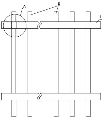
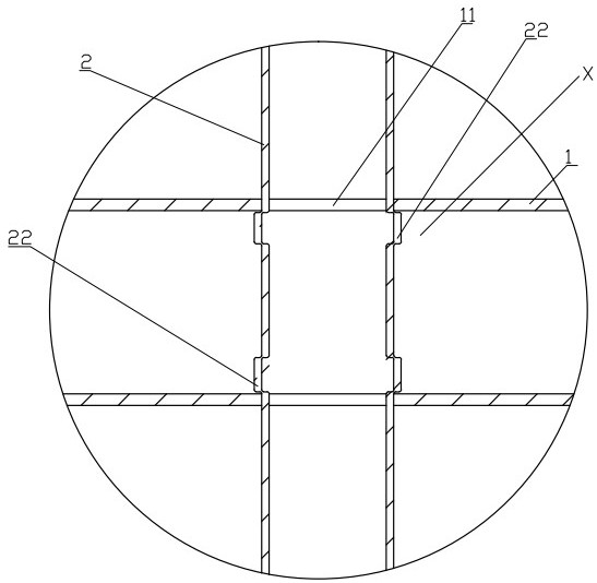
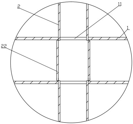
[0024] as attached figure 1 and figure 2 As shown, the embodiment of the quick-assembled guardrail provided by the present invention includes a plurality of crossbeams 1 arranged at intervals and arranged horizontally and longitudinal beams 2 arranged at intervals and arranged vertically. In this embodiment, the crossbeams and The longitudinal beams are all made of square tubes, and two cross beams are provided. The cross beams are provided with a plurality of insertion holes 11 arranged at intervals and vertically through, and the insertion holes of the adjacent upper and lower beams are vertically aligned. , on the opposite two pipe walls on the square pipe are processed opposite through holes, the two opposite through holes and the inner cavity of the square pipe between the two through holes jointly form the insertion hole, the longitud...


PUM


Abstract

The invention discloses a quick assembly type guardrail. The quick assembly type guardrail comprises a plurality of cross beams which are arranged at intervals and transversely arranged and longitudinal beams which are arranged at intervals and vertically arranged, wherein a plurality of inserting holes which are arranged at intervals and vertically run through are formed in the cross beams, and the inserting holes of the upper cross beam and the lower cross beam which are adjacent are vertically aligned; the longitudinal beams are inserted from the inserting holes to realize inserting connection of the longitudinal beams and the cross beams; the cross beams are provided with inserting sections; the inserting holes are positioned in the inserting sections; the inserting sections are provided with limiting cavities which protrude from the hole walls of the inserting holes to the peripheries; limiting bulges are arranged on the sections, inserted into the inserting holes, of the longitudinal beams; and the limiting bulges are propped against the cavity walls of the limiting cavities. The quick assembly type guardrail has the advantages and effects of being stable and firm in mounting, convenient and quick in mounting and good in corrosion resistance.

Description

technical field [0001] The invention relates to a quickly assembled guardrail. Background technique [0002] At present, the known guardrails are assembled and welded by materials such as iron, aluminum, and stainless steel. Assembling welding guardrails is not only troublesome and costly to process, but also the smoke and dust during assembly welding will cause environmental pollution and cause harm to the health of relevant personnel. In addition, the welding process causes defects such as deformation and corrosion of the pipe fittings, and the paint coating on the surface is seriously peeled off, resulting in high maintenance costs in the later period, and the need for repainting and other processes in the later period. [0003] Most of the existing guardrails are assembled manually, that is, after a plurality of holes are opened on the beam, at least two beams are placed in parallel so that the holes on the two beams are aligned, and then each longitudinal beam is manua...

Claims


Application Information

Patent Timeline
IPC IPC(8): E04H17/14
CPCE04H17/14
Inventor 杨义远白军伟
Owner 杨义远
Why Eureka
Try Eureka