Fireproof fluid machine

A technology of fluid machinery and fireproof boxes, which is applied in the direction of mechanical equipment, liquid fuel engines, and components of pumping devices for elastic fluids. Blockage, high safety, high convenience effect

Active Publication Date: 2020-10-13
福建兴万祥建设集团有限公司
View PDF6 Cites 4 Cited by
  • Summary
  • Abstract
  • Description
  • Claims
  • Application Information

AI Technical Summary

Problems solved by technology

[0003] During the use of the existing fan, due to the aging of the circuit and other reasons, there is the possibility of the motor spontaneously igniting. The air inlet is equip

Method used


Image

  • Fireproof fluid machine
  • Fireproof fluid machine
  • Fireproof fluid machine

Examples


Embodiment Construction

[0026] The present invention is described in further detail now in conjunction with accompanying drawing. These drawings are all simplified schematic diagrams, which only illustrate the basic structure of the present invention in a schematic manner, so they only show the configurations related to the present invention.

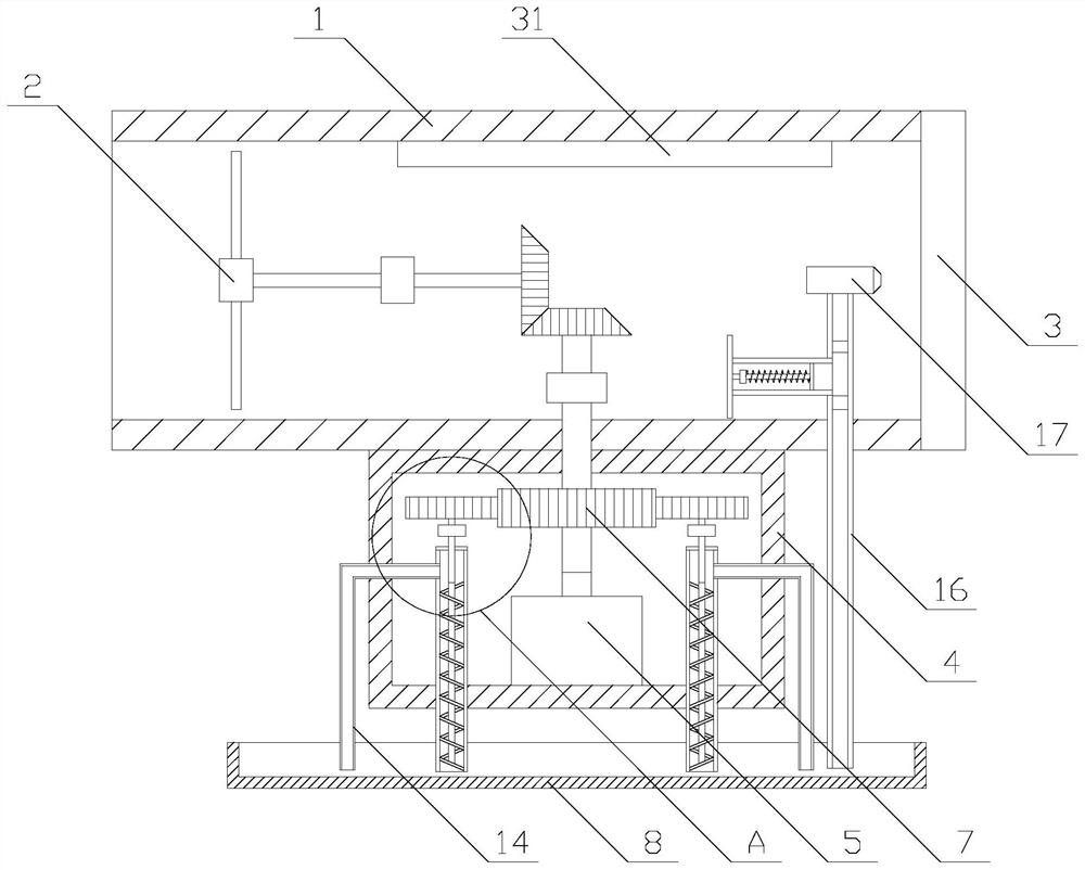
[0027] Such as Figure 1-2 As shown, a fireproof fluid machine includes a fixed pipe 1, a fan blade 2 and a protective net 3, the fixed pipe 1 is arranged horizontally, the fan blade 2 is arranged in the fixed pipe 1, and the protective net 3 is arranged in the One end of the fixed pipe 1, the main body is provided with a driving mechanism and an auxiliary mechanism;

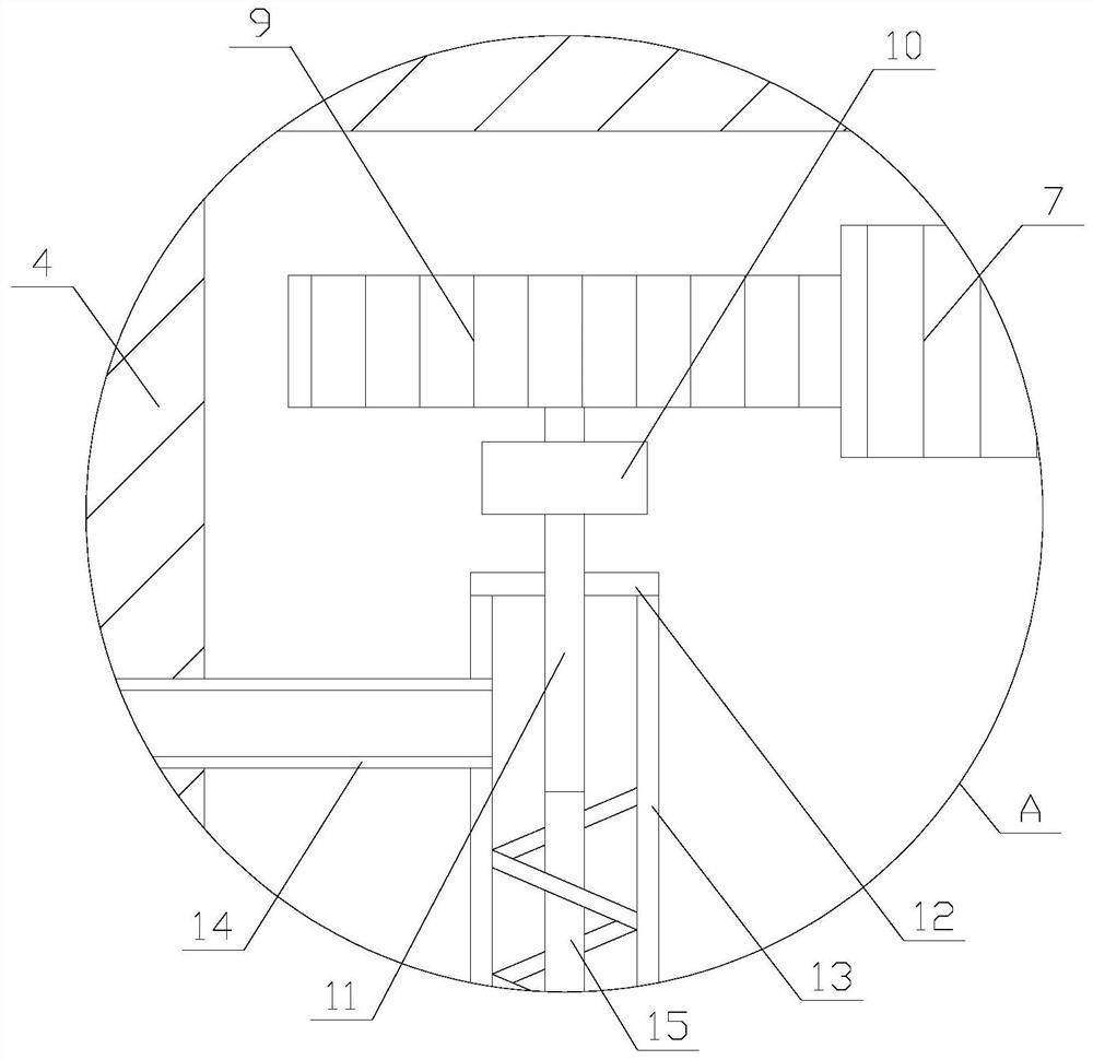
[0028] The drive mechanism includes a fireproof box 4, a drive motor 5, a transmission shaft 6, a drive gear 7, a water tank 8, a transmission assembly and two cooling assemblies, the fireproof box 4 is fixed on the bottom of the fixed pipe 1, and the drive motor 5 Located in the fireproof box...


PUM


Abstract

The invention relates to a fireproof fluid machine. The fireproof fluid machine comprises a fixing pipe, fan blades and a protective net, wherein the fixing pipe is horizontally arranged; the fan blades are arranged in the fixing pipe; the protective net is arranged at one end of the fixing pipe; a driving mechanism and an auxiliary mechanism are arranged on a body; the driving mechanism comprisesa fireproof box, a driving motor, a transmission shaft, a driving gear, a water tank, a transmission assembly and two cooling assemblies; each cooling assembly comprises a driven gear, a first bearing, a rotating shaft, a sealing ring, a connecting pipe, a water pipe, a screw, a through hole and a round hole; and the auxiliary mechanism comprises a guide pipe, a nozzle, an auxiliary pipe, a firstone-way valve, a second one-way valve and an auxiliary assembly. According to the fireproof fluid machine, the function of driving the fan blades to rotate is achieved through the driving mechanism,in addition, the function of cleaning the protective net is achieved through the auxiliary mechanism, and the protective net is prevented from being blocked.

Description

technical field [0001] The invention relates to the field of fans, in particular to a fireproof fluid machine. Background technique [0002] The fan is a machine that relies on the input mechanical energy to increase the gas pressure and discharge the gas. It is a driven fluid machine. Fan is the customary abbreviation for gas compression and gas conveying machinery in China. Fans are widely used in factories, mines, tunnels, cooling towers, vehicles, ships and buildings for ventilation, dust removal and cooling, as well as for ventilation and induction of boilers and industrial furnaces. Wind; cooling and ventilation in air-conditioning equipment and household electrical equipment; drying and sorting of grain, wind tunnel wind source and inflation and propulsion of hovercraft, etc. [0003] During the use of the existing fan, due to the aging of the circuit and other reasons, there is the possibility of the motor spontaneously igniting. The air inlet is equipped with a pr...

Claims


Application Information

Patent Timeline
IPC IPC(8): F04D25/08F04D29/58F04D29/70F04D19/00H02K9/00H02K5/04
CPCF04D19/002F04D25/082F04D29/5806F04D29/703F04D29/705H02K5/04H02K9/00
Inventor 张子辉
Owner 福建兴万祥建设集团有限公司
Why Eureka
Try Eureka