
Fault location method and system for high voltage direct current transmission line and direct current transmission line

A technology for direct current transmission lines and transmission lines, applied in the fault location of high-voltage direct current transmission lines, in the field of direct current transmission lines, can solve the problems of fault location dead zone and affect the accuracy of fault location, and achieve the goal of shortening the distance and eliminating the fault location dead zone Effect

Active Publication Date: 2021-06-25
HUNAN UNIV
View PDF0 Cites 0 Cited by
  • Summary
  • Abstract
  • Description
  • Claims
  • Application Information

AI Technical Summary

Problems solved by technology

[0005] Aiming at the deficiencies of the prior art, the present invention provides a fault location method and system for high-voltage direct current transmission lines to solve the problem of using wave velocity as an independent variable of the fault location equation, which affects the fault location accuracy and the fault location dead zone

Method used


Image

  • Fault location method and system for high voltage direct current transmission line and direct current transmission line
  • Fault location method and system for high voltage direct current transmission line and direct current transmission line
  • Fault location method and system for high voltage direct current transmission line and direct current transmission line

Examples


Embodiment 1

[0065] A fault location method for a high-voltage direct current transmission line provided by the present invention includes:

[0066] 1. Obtain the measured values ​​of electrical quantities at multiple measurement points on the DC transmission line. The measured values ​​of the electrical quantities are current measurement values ​​or current measurement values ​​and voltage measurement values.

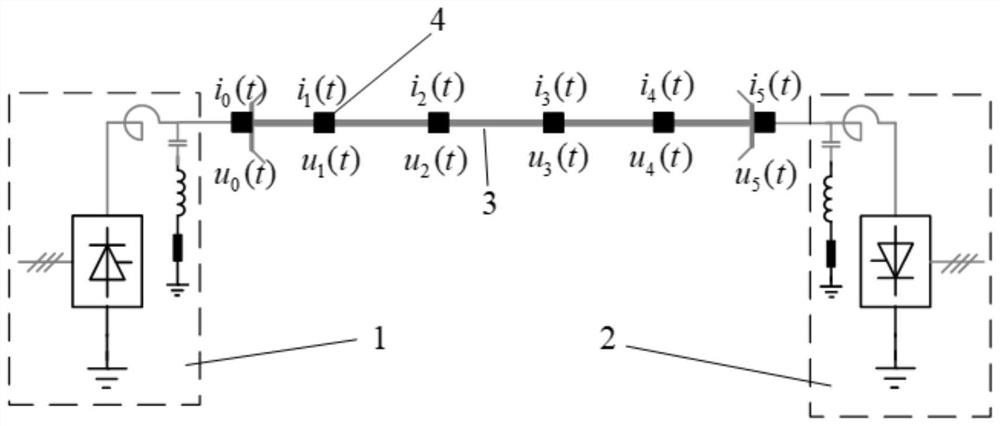
[0067] Such as figure 1 As shown, the HVDC transmission system includes a rectifier station 1, an inverter station 2, and a DC transmission line 3 connecting the rectification station 1 and the inverter station 2. The quantity measuring device 4 takes the installation position of each electrical quantity measuring device 4 as a measuring point, and obtains the voltage measurement value and current measurement value or current measurement value of each measurement point through the electrical quantity measurement device 4 . The measuring points on the direct current transmission li...

Embodiment 2

[0115] In order to take into account both economy and positioning accuracy, the total number of electrical quantity measuring devices in this embodiment is 6, such as figure 1 As shown, there is one at the head end and one at the end of the DC transmission line (the corresponding measurement point is M 0 , M 5 ), and set 4 along the DC transmission line in sequence (the corresponding measurement points are M 1 , M 2 , M 3 , M 4 ), and the measurement point M 1 , M 2 , M 3 , M 4 The distances from the head end of the DC transmission line are 0.2L, 0.4L, 0.6L and 0.8L respectively. This setting can ensure that when any point of the transmission line fails, the maximum distance between the measurement point and the fault point is limited within 0.2L, which can effectively improve the accuracy of the current measurement value or the initial wave head identification of the voltage reverse traveling wave, and improve the Fault location accuracy. In this embodiment, the uni...


PUM


Abstract

The invention discloses a fault location method and system for a high-voltage direct current transmission line. The polarity and arrival time of the wave head are obtained by using the electrical quantity measured at each measurement point along the transmission line, and the fault section location criterion is established, and the fault precise location is established. According to the wave head polarity, the fault section can be discriminated, and the fault location can be accurately obtained by solving the positioning equation. The proposed distributed positioning scheme uses multi-point measurement of electrical quantities along the transmission line to establish a fault positioning equation. The positioning principle is simple, reliable, and highly accurate. There is no positioning dead zone, and the dependence of positioning accuracy on line parameters is eliminated.

Description

technical field [0001] The invention belongs to the technical field of high-voltage transmission line fault location, and in particular relates to a fault location method and system for a high-voltage direct current transmission line and a direct current transmission line. Background technique [0002] Compared with traditional AC transmission, DC transmission has economic and technical advantages such as narrow line corridor, low loss, transmission capacity not limited by system operation, and cross-regional asynchronous networking. Since the first direct current transmission project was put into operation in the 1950s, a wave of its application has been gradually launched in the power system, and the transmission level and transmission capacity have been continuously improved. [0003] As the lifeblood of the power system, the DC transmission line is the most prone to failure in the power system. If it fails, it will cause a series of serious consequences such as a decreas...

Claims


Application Information

Patent Timeline
Patent Type & Authority Patents(China)
IPC IPC(8): G01R31/08
CPCG01R31/085G01R31/088Y04S10/52
Inventor 褚旭吕昊泽孙锦琛鲍泽宏殷高文罗鑫锦
Owner HUNAN UNIV
Learn More