High-frequency welded pipe shape adjusting and self-diagnosing device based on encoders

A high-frequency welded pipe and encoder technology, which is applied in the direction of instruments, simulators, control/adjustment systems, etc., can solve the problems of inaccurate forming, cumbersome adjustment process, long time, etc., and achieve the effect of ensuring the forming quality

Pending Publication Date: 2020-10-13
SINOPEC OILFIELD EQUIP CORP
View PDF0 Cites 0 Cited by
  • Summary
  • Abstract
  • Description
  • Claims
  • Application Information

AI Technical Summary

Problems solved by technology

[0002] At present, for most high-frequency welded pipe manufacturing enterprises, there is no simple, safe, visual, intuitive and effective complete numerical method to quickly and accurately complete the adjustment of steel pipes, and can dynamically monitor the position of equipment during production with digital display status State, usually the manual static method is commonly used to adjust the type, relying on the steel ruler to measure, manually read the value, repeatedly compare the gap parameters required by the process, and constantly move the equipment parts to complete the adjustment work, which is not accurate enough, resulting in large errors and adjustment. The process is cumbersome and takes a long time, resulting in a waste of time. At the same time, it is impossible to observe the position and status of equipment components in real time during production, and it is impossible to correct deviations in time, to ensure the quality of steel pipe forming, and to meet the requirements of rapid and precise adjustment
The work consumes a lot of manpower, the labor intensity is high, and it cannot meet the production safety guarantee, so that the equipment runs with inaccurate molding problems during the start-up process, resulting in unstable molding and fluctuations after the production line is started, which increases the number of search problems. Difficulty and processing solve the process time, affect the production schedule, and cause production cost and time waste

Method used


Image

  • High-frequency welded pipe shape adjusting and self-diagnosing device based on encoders

Examples


Embodiment Construction

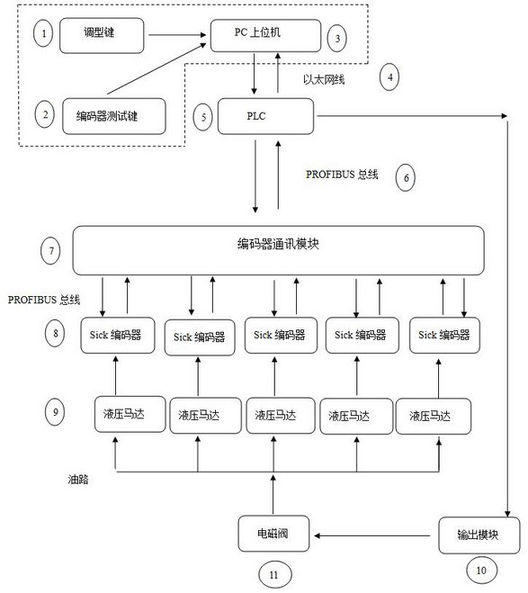
[0009] Attached below figure 1 Specific embodiments of the present invention will be further described.

[0010] see figure 1 , PC host computer is used to set instructions and various parameters, and PLC converts signal processing into switch variable signals and transmits them to the output module; the output module controls the opening of the hydraulic motor by controlling the solenoid valve; each hydraulic motor is equipped with a SICK digital code The SICK digital encoder collects the position signal of the hydraulic motor; the encoder communication module processes the received signal of the SICK digital encoder; and then it is processed by the PLC and displayed on the PC host computer. There are two functions of profile adjustment and encoder test on the PC host computer.

[0011] When adjusting the type, just press the adjustment key 1, and on the PC host computer 3 interface, 8 groups of multiple encoders installed on different positions of the main machine (upper r...


PUM


Abstract

The invention discloses a high-frequency welded pipe shape adjusting and self-diagnosing device based on encoders. A PC upper computer is used for setting instructions and all parameters, and a PLC processes signals into switch variable signals and transmits the switch variable signals to an output module; the output module controls the starting of a hydraulic motor by controlling an electromagnetic valve; each hydraulic motor is provided with one SICK digital encoder, and the SICK digital encoders collect position signals of the hydraulic motors; an encoder communication module processes thereceived signals of the SICK digital encoders; and then the signals are processed by the PLC and displayed on the PC upper computer. The numerical value of the on-site encoder can be read to achieve rapid and accurate shape adjustment, meanwhile, the specific position data of all encoders in the production process can be monitored in real time, the faults of the on-site encoders can be diagnosed at any time, and the self-diagnosis of an encoder system is realized.

Description

technical field [0001] The invention belongs to the field of steel pipe production, and in particular relates to a high-frequency welded pipe adjustment and diagnosis device. Background technique [0002] At present, for most high-frequency welded pipe manufacturing enterprises, there is no simple, safe, visual, intuitive and effective complete numerical method to quickly and accurately complete the adjustment of steel pipes, and can dynamically monitor the position of equipment during production with digital display status State, usually the manual static method is commonly used to adjust the type, relying on the steel ruler to measure, manually read the value, repeatedly compare the gap parameters required by the process, and constantly move the equipment parts to complete the adjustment work, which is not accurate enough, resulting in large errors and adjustment. The process is cumbersome and takes a long time, resulting in a waste of time. At the same time, it is impossi...

Claims


Application Information

Patent Timeline
Patent Type & Authority Applications(China)
IPC IPC(8): G05B19/042
CPCG05B19/0428G05B2219/24054
Inventor 陈志强钟存福石振聪梁刚陈亮沈袆军左兰兰张新芳李俊华蔡小青
Owner SINOPEC OILFIELD EQUIP CORP
Why Eureka
Try Eureka