Feeding device for animal husbandry

A technology for animal husbandry and feeding troughs, applied in the field of animal husbandry, can solve the problems of low operation efficiency, manual processing, and difficulty in moving, etc., and achieve the effects of improving operation efficiency, improving stability and uniform perfusion.

Inactive Publication Date: 2020-10-16
马迎松
View PDF0 Cites 1 Cited by
  • Summary
  • Abstract
  • Description
  • Claims
  • Application Information

AI Technical Summary

Problems solved by technology

[0002] The traditional feeding trough is bulky and difficult to move, and it is inconvenient to place and set up on the pasture. At the same time, the feeding feed needs to be processed manually, and the work efficiency is not high

Method used


Image

  • Feeding device for animal husbandry
  • Feeding device for animal husbandry
  • Feeding device for animal husbandry

Examples


Embodiment 1

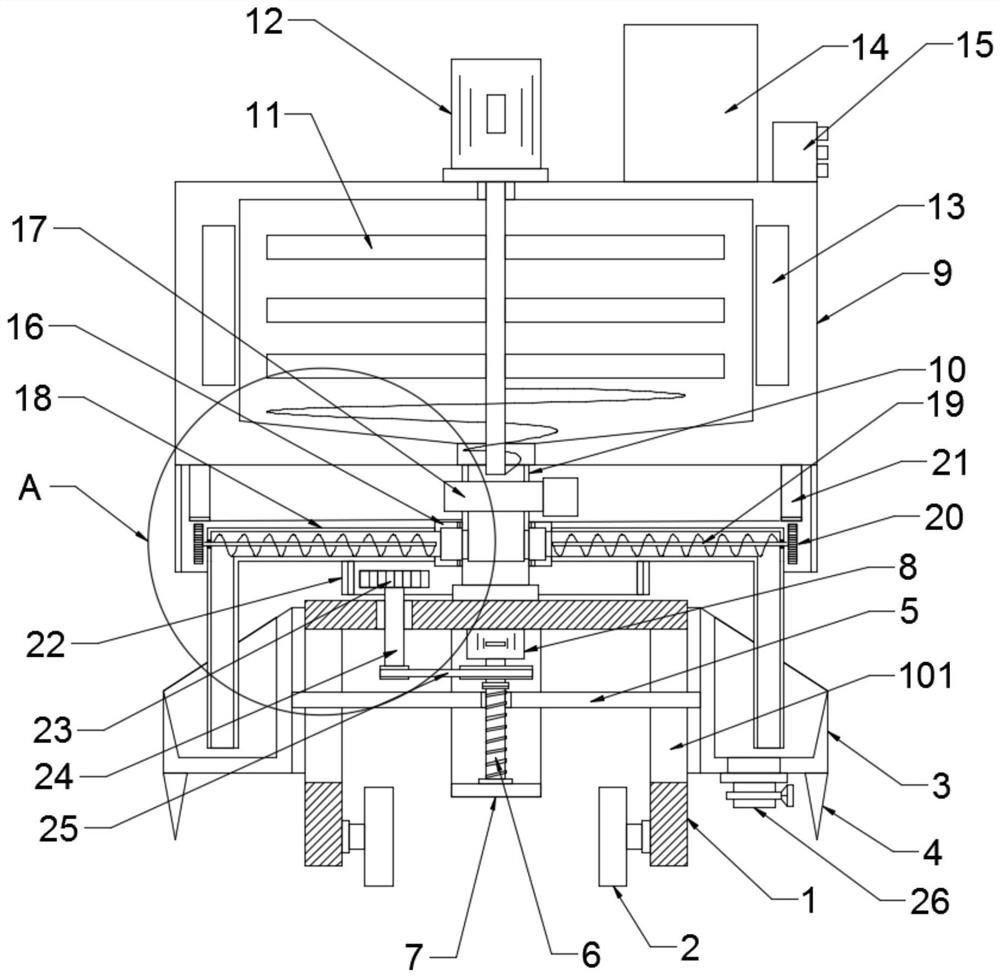
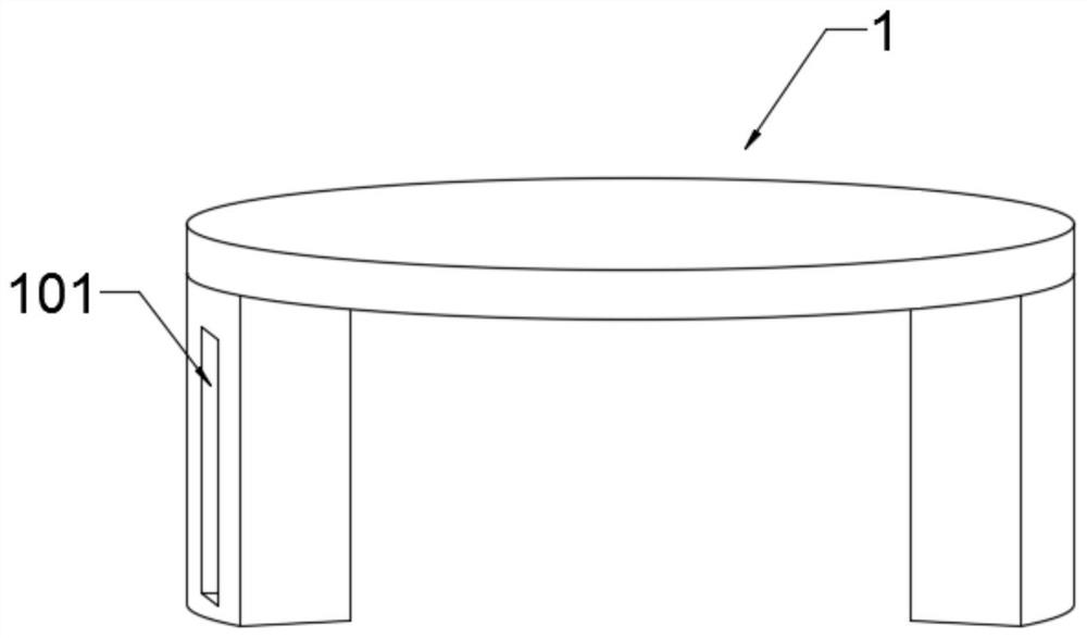
[0020] see Figure 1-4 , in an embodiment of the present invention, a feeding device for animal husbandry, comprising a moving seat 1, a feeding trough 3 and a processing box 9; the inner side of the moving seat 1 is provided with rollers 2 to facilitate the movement of the device; the outer side of the moving seat 1 is covered A feeding trough 3 is provided, and the feeding trough 3 is an annular feeding trough; the inner side of the feeding trough 3 is fixedly connected with a lifting plate 5, and the lifting plate 5 runs through the side wall of the moving seat 1, and the side wall of the moving seat 1 is provided for the lifting plate 5 to slide up and down The chute 101, the middle part of the lifting plate 5 runs through a screw mandrel 7, the screw mandrel 7 is threadedly connected with the lifting plate 5, the lower end of the screw mandrel 7 is connected with the mounting frame 7 through the bearing seat, and the mounting frame 7 is fixedly connected with the mobile se...

Embodiment 2

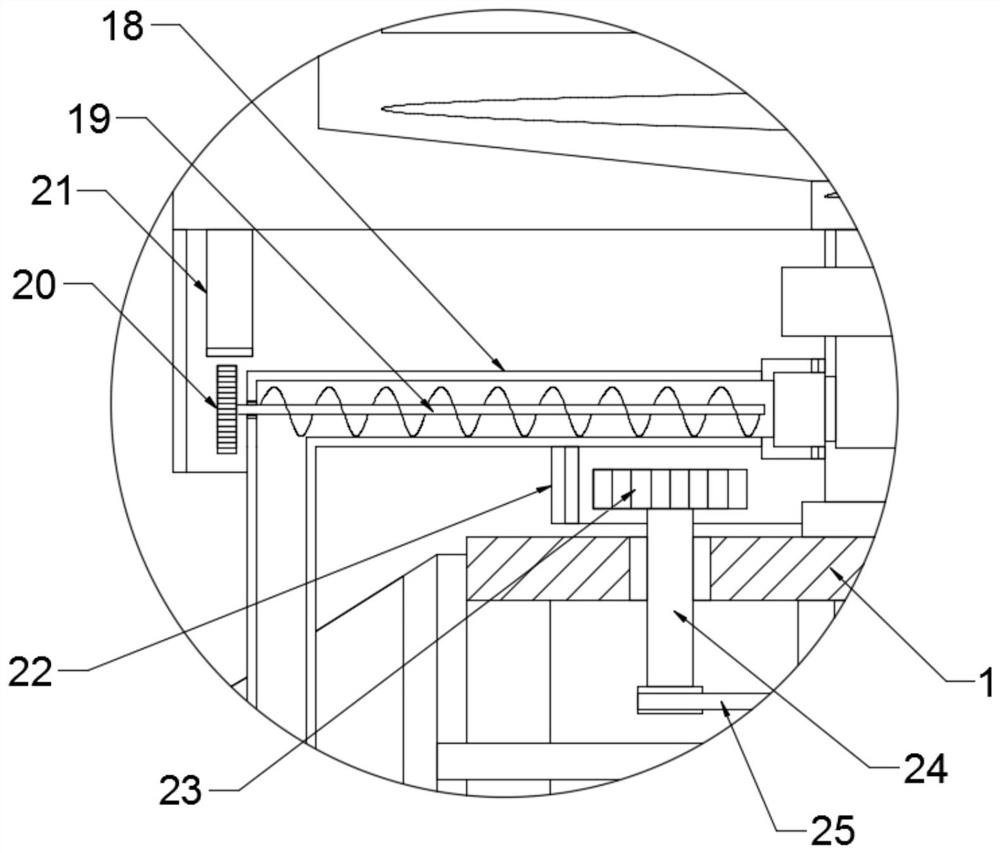
[0023] The difference between this embodiment and Embodiment 1 is: for convenience, the feed is evenly poured into the feeding trough 3; the lower end of the processing box 9 is fixedly connected with a support cylinder 10, the support cylinder 10 communicates with the inner cavity of the processing box 9, and the support cylinder 19 is connected to the inner cavity of the processing box 9 A solenoid valve 17 is provided at the connection of the processing box 9, and the solenoid valve 17 is connected with the controller 15, and the lower end of the support cylinder 10 is fixedly connected with the moving seat 1; the outer side of the support cylinder 10 is provided with a sleeve 16, and the sleeve 16 passes through the bearing sleeve It is rotatably connected with the support tube 10, and the side wall of the support tube 10 is provided with a communication hole, and the sleeve 16 communicates with the inner cavity of the support tube 10 through the communication hole; The pip...


PUM


Abstract

The invention discloses a feeding device for animal husbandry. The feeding device comprises moving seats, feeding troughs and a processing box. Roller are arranged inside the moving seats, the movingseats are sleeved with the feeding troughs, a lifting plate is fixedly connected inside the feeding troughs, a screw penetrates through the middle of the lifting plate, and the upper end of the screwis connected with a screw motor through a coupling; fixing cones are fixedly connected with the bottoms of the feeding troughs. The moving seats, the rollers, the feeding troughs, the fixing cones, the lifting plate and the screw are arranged, so that the whole feeding device can be conveniently fixed and moved in the pasture, stability of the feeding device is improved, and livestock can eat conveniently; a support cylinder, a sleeve, discharging pipes, a second gear ring, a transmission gear, a transmission shaft, a transmission belt, spiral feeding rollers, rolling gears and first gear rings are arranged, the feeding troughs are fixed and feed is uniformly poured, so that operation efficiency is improved.

Description

technical field [0001] The invention relates to the field of animal husbandry, in particular to a feeding device for animal husbandry. Background technique [0002] The traditional feeding trough is heavy and difficult to move, and it is inconvenient to place and set up on the pasture. At the same time, the feeding feed needs to be processed manually, and the work efficiency is not high. Contents of the invention [0003] The object of the present invention is to provide a feeding device for animal husbandry to solve the problems raised in the above-mentioned background technology. [0004] To achieve the above object, the present invention provides the following technical solutions: [0005] A feeding device for animal husbandry, comprising a moving seat, a feeding trough and a processing box; rollers are arranged on the inner side of the moving seat, a feeding trough is set on the outer side of the moving seat, a lifting plate is fixedly connected to the inner side of t...

Claims


Application Information

Patent Timeline
Patent Type & Authority Applications(China)
IPC IPC(8): A01K5/00A01K5/02A01K39/012A01K39/014
CPCA01K5/004A01K5/02A01K5/0258A01K39/0125A01K39/014
Inventor 马迎松
Owner 马迎松
Why Eureka
Try Eureka