Desk capable of preventing myopia
A technology for myopia and desks, applied in the field of desks, can solve problems that affect students' learning and cannot guarantee students' anti-myopia function, and achieve the effects of reducing the probability of myopia, high adaptability and diversity, and improving comfort
- Summary
- Abstract
- Description
- Claims
- Application Information
AI Technical Summary
Problems solved by technology
Method used
Image
Examples
Embodiment 1
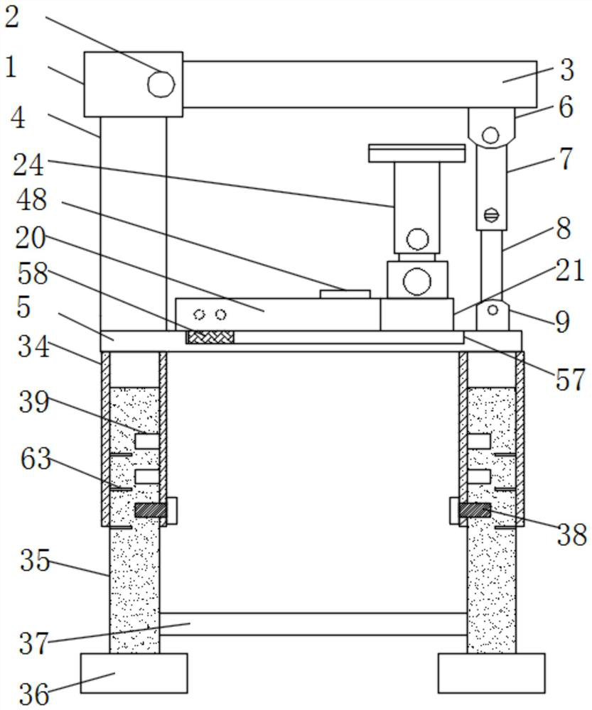
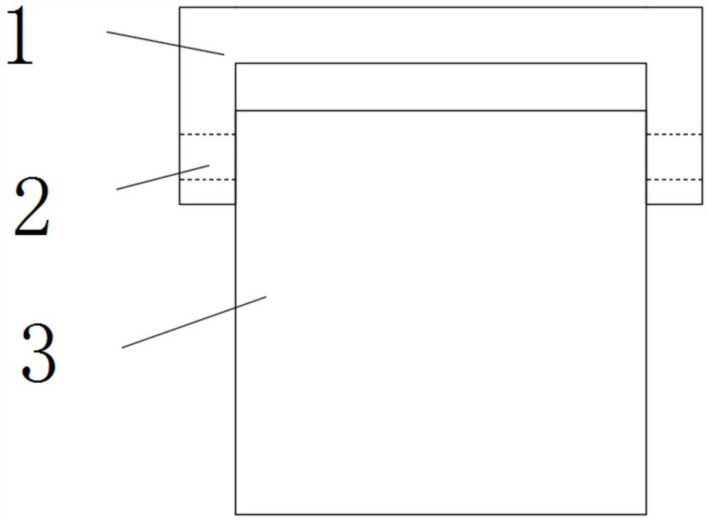
[0036] see Figure 1-9 According to an embodiment of the present invention, a desk capable of preventing myopia includes a connecting frame 1, which is movably connected to a table board 3 through a movable shaft 2, and the shape design of the connecting frame 1 is similar to a U shape, so The bottom of the connecting frame 1 is fixedly connected with a support rod 4, the bottom of the support rod 4 is fixedly connected with a support plate 5, and the bottom of the side of the table 3 away from the support rod 4 is fixedly connected with two Fixed block one 6, described fixed block one 6 is movably connected with the top of sleeve 7, the inside of described sleeve 7 is provided with movable bar 8, and the bottom of described movable bar 8 is movably connected with fixed block two 9, described The second fixed block 9 is connected with the support plate 5;
[0037] The two sides of described movable bar 8 are provided with chute 10, and the inside of described chute 10 is prov...
Embodiment 2
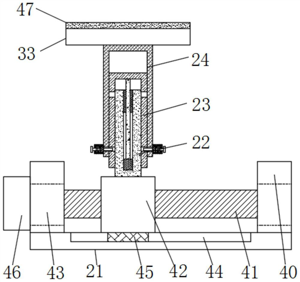
[0041] see Figure 1-3 , the adjustment mechanism includes a support block 40, a screw rod two 41, a moving block one 42 and a bearing 43, the top two sides of the slide plate 21 are fixedly connected with a support block 40, and the support block 40 is connected to the screw rod two by the bearing 43 41 is movably connected, the outer surface of the screw rod 2 41 is threadedly connected with a moving block 1 42, the bottom end of the screw rod 1 22 is fixedly connected with the moving block 42, and the top of the slide plate 21 has a limiting groove 1 44 , the bottom of the moving block one 42 is fixedly connected to the first limiting block 45, the first limiting block 45 is located in the first limiting groove 44 and matches the first limiting groove 44, the second screw 41 One end extends to the outside of the support block 40 and is fixedly connected with the rotating block 46. The adjustment mechanism can adjust the position of the limiting plate 33, so that the limitin...
Embodiment 3
[0043] see figure 1 and Image 6 , the fixed mechanism includes a fixed box 2 48, a moving block 2 49, a spring 3 50, a limit frame 51, a moving rod 2 52 and a fixing groove 53, and the top of the support plate 5 is fixedly connected with a fixed box 2 48, so The inside of the fixed box 2 48 is connected with the moving block 2 49 through the spring 3 50, and the side of the moving block 2 49 away from the spring 3 50 is fixedly connected with the moving bar 2 52, and the two ends of the fixed box 48 The port is fixedly connected to the limit frame 51, the inside of the slide bar 20 is provided with a fixed slot 53 matching the second moving bar 52, the top of the fixed box 2 48 has an opening 54, and the opening 54 is provided with Push block one 55, the bottom of the push block one 55 is fixedly connected with the moving block two 49, the top of the push block one 55 is fixedly connected with the push block two 56, and the fixing mechanism can fix the slide bar 20, thereby ...
PUM
 Abstract
Description
Claims
Application Information
 - R&D
- Intellectual Property
- Life Sciences
- Materials
- Tech Scout
- Unparalleled Data Quality
- Higher Quality Content
- 60% Fewer Hallucinations
Browse by: Latest US Patents, China's latest patents, Technical Efficacy Thesaurus, Application Domain, Technology Topic, Popular Technical Reports.
© 2025 PatSnap. All rights reserved.Legal|Privacy policy|Modern Slavery Act Transparency Statement|Sitemap|About US| Contact US: help@patsnap.com


