Wire conduction ultrasonic bronchoscope for liquefying thick sputum
A bronchoscope and ultrasound technology, applied in the field of medical devices, can solve the problems of patients not being rescued in time, tracheal tissue damage, pulmonary edema, etc., to avoid tracheal tissue damage or waste emphysema, achieve quick results, and improve the effect of treatment rate.
- Summary
- Abstract
- Description
- Claims
- Application Information
AI Technical Summary
Problems solved by technology
Method used
Image
Examples
Embodiment 1
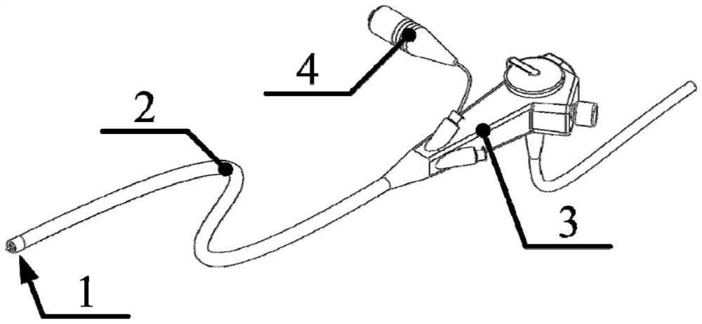
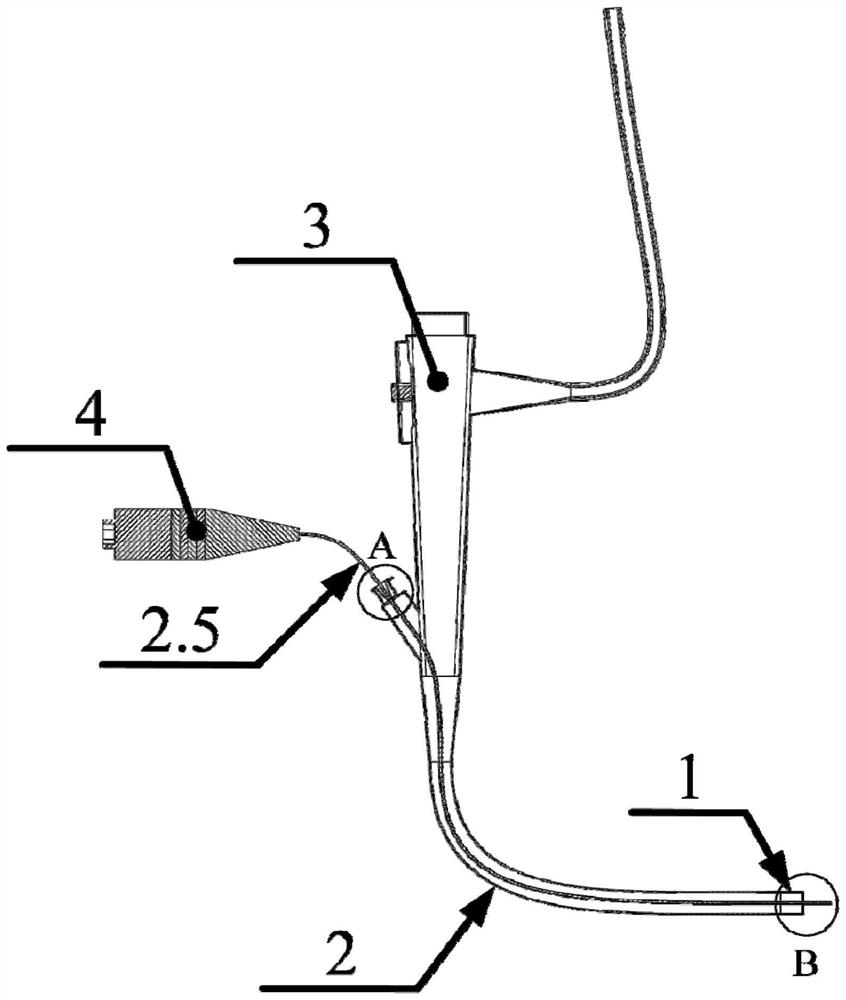
[0033] Such as figure 1 and figure 2 As shown, a wire conduction ultrasonic bronchoscope for liquefying thick sputum of the present invention comprises a probe (1), a catheter (2), a handle (3) and a transducer (4), the probe (1), the catheter (2), the connection relationship between the handle (3) and the transducer (4) is: the probe (1) is connected to one end of the conduit (2), the other end of the conduit (2) is connected to the handle (3), and the handle (3) ) is connected to the transducer (4).
[0034] The catheter (2) includes a conduction wire (2.5). One end of the conduction wire (2.5) protrudes from the handle (3) and is connected to the transducer (4), and the other end protrudes from the probe (1).
[0035] In this embodiment, when the invention is used to suck sputum on a patient, the bronchoscope goes deep into the patient's lungs or trachea, and the transducer (4) applies an alternating current of ultrasonic frequency to generate ultrasonic vibration, and t...
Embodiment 2
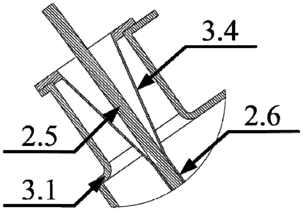
[0037] Such as image 3 and Figure 4 As shown, the present invention is a wire-conduction ultrasonic bronchoscope for liquefying thick sputum. The catheter (2) includes a conduction line (2.5) and a conduction line tube (2.6), and the conduction line (2.5) is inserted in the conduction line tube (2.5). 2.6).
[0038] The handle (3) includes a handle shell (3.1) and a conduction wire entrance (3.4), and the conduction line entrance (3.4) is installed on the handle shell (3.1).
[0039]The connection relationship between the conduction line tube (2.6), the conduction line entrance (3.4) and the probe (1) is: one end of the conduction line tube (2.6) is connected to the conduction line entrance (3.4), and the other end is connected to the probe (1) connected.
Embodiment 3
[0041] Such as Figure 5 As shown, the catheter (2) includes an outer catheter (2.1), an instrument tube (2.2), a first guiding line (2.3), a second guiding line (2.4), a conducting line (2.5), and a conducting line tube (2.6) and imaging line (2.7), the outer catheter (2.1), instrument tube (2.2), first guiding line (2.3), second guiding line (2.4), conducting line (2.5), conducting line tube (2.6) and The positional relationship of the imaging line (2.7) is: the conduction line (2.5) is inserted into the conduction line tube (2.6), the instrument tube (2.2), the first guide line (2.3), the second guide line (2.4), the conduction line tube (2.6 ) and the camera line (2.7) are inserted into the outer catheter (2.1) in parallel.
[0042] Such as Figure 6 and Figure 7 As shown, the first guide line (2.3) includes a first optical fiber bundle (2.3.1) and a first optical fiber lamp (2.3.2), and one end of the first optical fiber bundle (2.3.1) is connected to the first optica...
PUM
 Abstract
Description
Claims
Application Information
 - R&D
- Intellectual Property
- Life Sciences
- Materials
- Tech Scout
- Unparalleled Data Quality
- Higher Quality Content
- 60% Fewer Hallucinations
Browse by: Latest US Patents, China's latest patents, Technical Efficacy Thesaurus, Application Domain, Technology Topic, Popular Technical Reports.
© 2025 PatSnap. All rights reserved.Legal|Privacy policy|Modern Slavery Act Transparency Statement|Sitemap|About US| Contact US: help@patsnap.com


