Mitral valve repair system

A repair system and mitral valve technology, applied in the direction of the valve ring, heart valve, catheter, etc., can solve the problems of insufficient stability and poor long-term effect of the clamping device, and achieve improved surgical safety, large torque, and reduced heart failure. interference effect

Pending Publication Date: 2020-10-16
石家庄帝中医疗器械科技有限公司
View PDF0 Cites 0 Cited by
  • Summary
  • Abstract
  • Description
  • Claims
  • Application Information

AI Technical Summary

Problems solved by technology

However, in the follow-up observation of patients, it was found that the clamping device has the disadvantages of insufficient stability and poor long-term effect

Method used


Image

  • Mitral valve repair system
  • Mitral valve repair system
  • Mitral valve repair system

Examples


no. 1 example

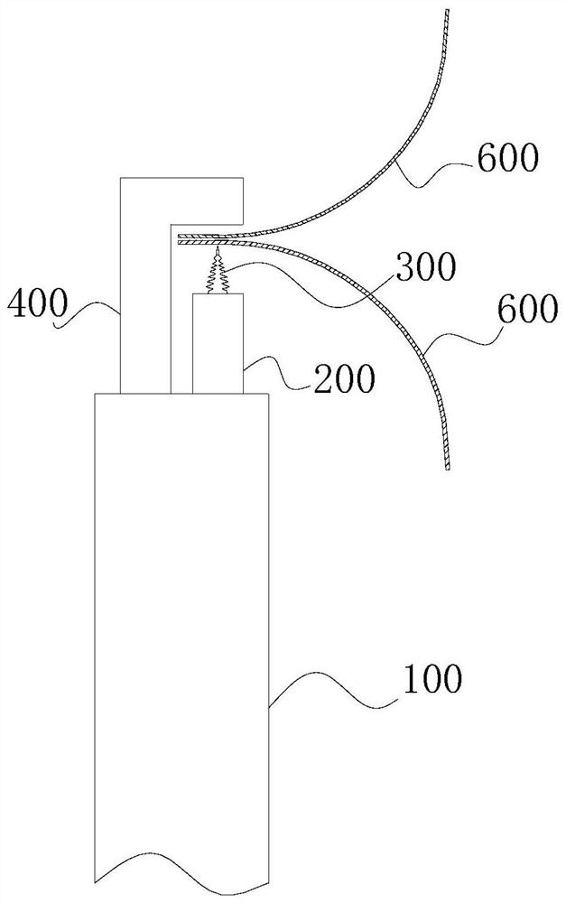
[0042] figure 1 It is a schematic structural diagram of the mitral valve repair system provided by the first embodiment of the present invention. Please refer to figure 1 , the present embodiment provides a mitral valve repair system, which includes a delivery sheath 100 , a guide tube 200 , a puncture member 300 and a support member 400 .

[0043] Wherein, the support member 400 is arranged at the outlet end of the delivery sheath 100; the guide tube 200 is arranged in the delivery sheath 100, and the puncture member 300 is movably arranged in the guide tube 200; the guide tube 200 is used to guide the puncture member 300 to the delivery sheath The outlet end of the tube 100 abuts against the support member 400, and the puncture member 300 is used to connect the anterior leaflet and the posterior leaflet of the mitral valve.

[0044] Wherein, the piercing member 300 can be movably arranged in the guide tube 200 , or can be detachably installed at the end of the guide tube 2...

no. 2 example

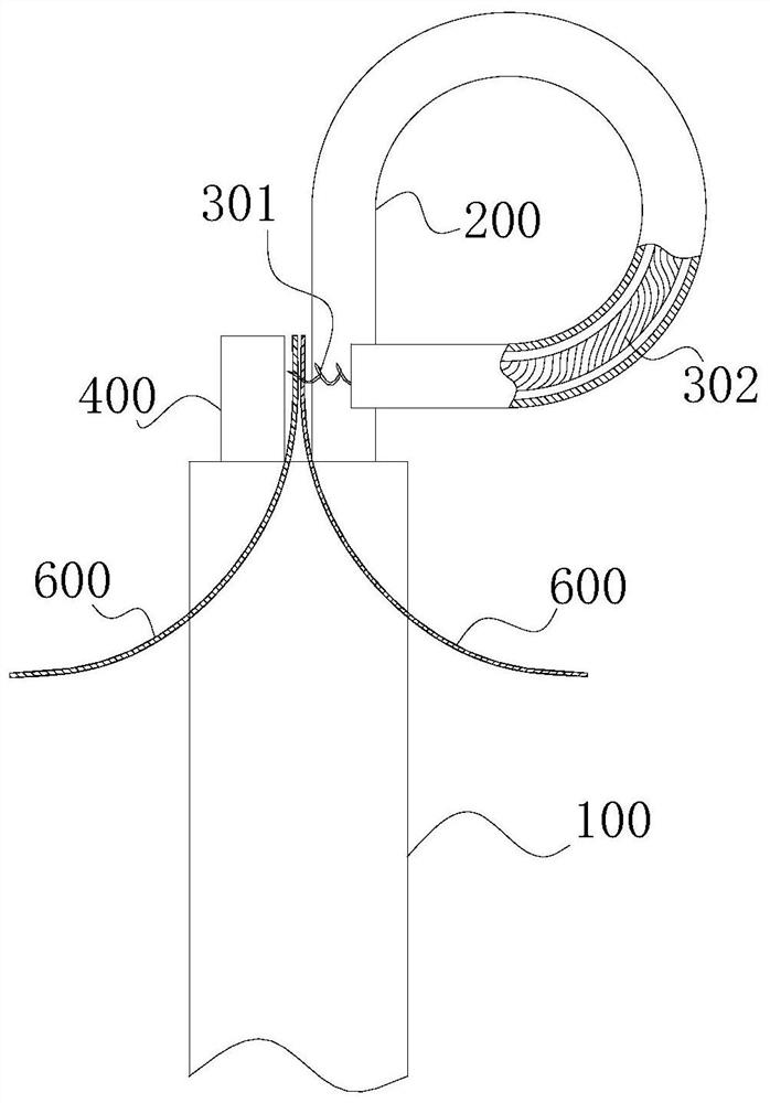
[0050] figure 2 It is a schematic structural diagram of the mitral valve repair system provided by the second embodiment of the present invention. Please refer to figure 2 , this embodiment provides a mitral valve repair system, which is substantially the same as the mitral valve repair system of the first embodiment, the difference between the two is that the puncture member 300 in the mitral valve repair system of this embodiment includes a puncture spring 301 and pushing steel cable 302;

[0051] Further, as figure 2 As shown, piercing spring 301 is made of cobalt-based alloy material.

[0052] Further, as figure 2 As shown, the curvature of the guide tube 200 can be adjusted.

[0053] Wherein, the outer diameter of the piercing spring 301 is preferably set to 2.5 mm to 3.5 mm, and the length is preferably set to 4 mm to 8 mm.

no. 3 example

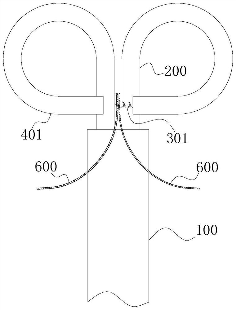
[0055] image 3 It is a schematic structural diagram of the mitral valve repair system provided by the third embodiment of the present invention. Please refer to image 3 , this embodiment provides a mitral valve repair system, which is substantially the same as the mitral valve repair system of the first embodiment or the second embodiment, the difference between the two lies in the support in the mitral valve repair system of this embodiment The member 400 includes a push tube 401; the curvature of the push tube 401 can be adjusted.


PUM


Abstract

The invention provides a mitral valve repair system, and relates to the technical field of medical instruments. The mitral valve repair system comprises a conveying sheath tube, a guide tube, a puncture part and a supporting piece. The supporting piece is arranged at the outlet end of the conveying sheath tube; the guide tube is arranged in the conveying sheath tube, and the puncture part is movably arranged in the guide tube; the guide tube is used for guiding the puncture part to the outlet end of the conveying sheath tube and abutting against the supporting piece, and the puncture part is used for enabling the anterior lobe and the posterior lobe of the mitral valve to be connected. Compared with a conventional clamping repair method, the mitral valve repair system has the advantages that connection repair of the anterior lobe and the posterior lobe of the mitral valve is achieved through the puncture part, and the closing stability of the mitral valve and the use long-term effect of the mitral valve repair system are greatly improved. Moreover, the puncture part can be designed to be small and light, operation is convenient, interference to the heart is reduced, and operation safety is improved.

Description

technical field [0001] The invention relates to the technical field of medical devices, in particular to a mitral valve repair system. Background technique [0002] The mitral valve is the valve between the left atrium and the left ventricle. When the mitral valve is not closed completely, blood can flow back to the left atrium, that is, mitral valve regurgitation occurs, which will cause a series of pathological changes and clinical symptoms of the heart. Symptoms, which can lead to heart failure in severe cases. [0003] There are various types of surgery for the above conditions. Among them, the classification according to the operation method includes surgical thoracotomy and minimally invasive interventional operation, and the classification according to the valve treatment method includes mitral valve repair and valve replacement. Clinically, for patients who are elderly, have a history of thoracotomy, poor heart function, and multiple organ insufficiency, and their ...

Claims


Application Information

Patent Timeline
Patent Type & Authority Applications(China)
IPC IPC(8): A61F2/24A61B17/34
CPCA61B17/3415A61B17/3417A61B2017/3454A61F2/2442A61F2/246A61F2/2466
Inventor 徐靖王耀鹏
Owner 石家庄帝中医疗器械科技有限公司
Why Eureka
Try Eureka