A ball valve auxiliary fit installation equipment

A technology for installing equipment and ball valves, used in metal processing equipment, metal processing, manufacturing tools, etc., can solve the problems of low ball embedding rate, cumbersome manual operation, affecting the production efficiency of ball valves, etc., and achieve easy collection and high ball embedding rate. , easy to embed the effect

Active Publication Date: 2022-01-04
HANGZHOU DONGCHEN HEATING POWER AUX
View PDF10 Cites 0 Cited by
  • Summary
  • Abstract
  • Description
  • Claims
  • Application Information

AI Technical Summary

Problems solved by technology

[0006] In order to overcome the disadvantages that currently in the process of making ball valves, the staff need to use manpower to hammer the ball into the valve body, the manual operation is cumbersome, and the ball embedding rate is not high, which affects the production efficiency of the ball valve. Therefore, the technology of the present invention The problem is: to provide a ball valve that can be automatically unloaded and easily embedded to assist with the installation equipment

Method used


Image

  • A ball valve auxiliary fit installation equipment
  • A ball valve auxiliary fit installation equipment
  • A ball valve auxiliary fit installation equipment

Examples


Embodiment 1

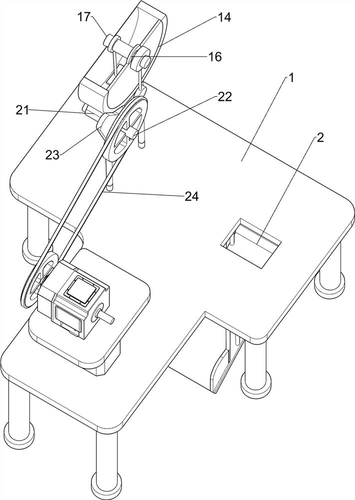
[0028] Such as Figure 1-3 As shown, a ball valve auxiliary installation equipment includes a workbench 1, a placement frame 3, a discharge mechanism 4, a pressing mechanism 6, and a slideway 5. A blanking hole 2 is opened on the right front of the top of the workbench 1, and the workbench 1. There is a placement frame 3 on the right side of the top, and the placement frame 3 is located above the blanking hole 2. The top of the workbench 1 is provided with a discharge mechanism 4. The discharge mechanism 4 is located on the left side of the placement frame 3. The bottom of the workbench 1 is provided with a slideway. 5. The slideway 5 is located below the blanking hole 2. A pressing mechanism 6 is arranged on the top of the workbench 1. The pressing mechanism 6 is located on the rear side of the discharging mechanism 4. The pressing mechanism 6 cooperates with the placement frame 3.

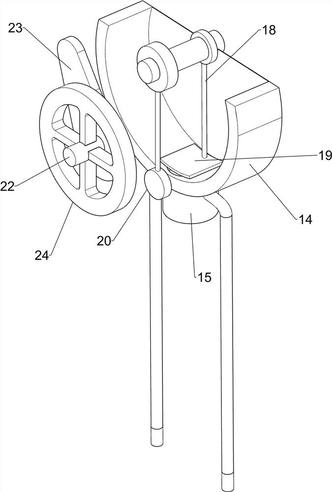
[0029] The discharge mechanism 4 includes a guide sleeve 41, a moving rod 42, a pull rod 43, ...

Embodiment 2

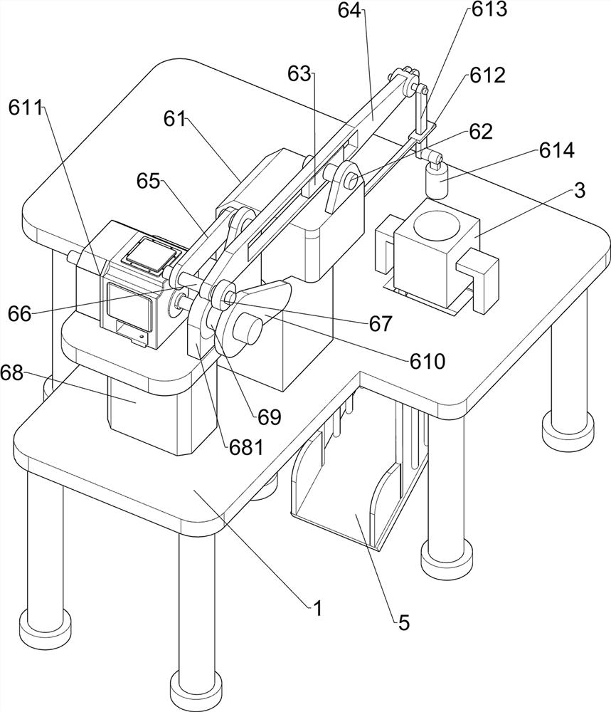
[0033] Such as Figure 4-7 As shown, on the basis of Embodiment 1, an auxiliary fitting installation device for a ball valve also includes a first bearing seat 7, a third rotating shaft 8, a second bearing seat 9, a fourth rotating shaft 10, and a fifth rotating shaft 11. The gear 12 and the crank handle 13. The right side of the top of the workbench 1 is symmetrically arranged with the first bearing seat 7 about the central axis of the placement frame 3. The two first bearing seats 7 are located on the front side of the placement frame 3. The two first bearing seats 7 are all provided with a third rotating shaft 8, and the right side of the top of the workbench 1 is symmetrically arranged with a second bearing seat 9 about the central axis of the placement frame 3. The second bearing seat 9 is located at the rear side of the placement frame 3, and the two second bearing seats 9 are provided with a fourth rotating shaft 10, the fifth rotating shaft 11 is connected between the ...


PUM


Abstract

The invention belongs to the technical field of ball valve manufacture, and in particular relates to a ball valve auxiliary matching installation equipment. Provides a ball valve that can be automatically unloaded and is conveniently embedded to assist in the installation of equipment. A ball valve auxiliary installation equipment, comprising: a workbench, a blanking hole is opened on one side of the top of the workbench, and a placing frame is arranged on the top of the workbench directly above the blanking hole; a discharge mechanism is placed close to the knuckle position of the top of the workbench The position of the frame is equipped with a discharge mechanism, which cooperates with the placement frame; the slideway, the bottom of the worktable is located directly below the blanking hole, and a slideway is provided; the pressing mechanism, the top of the workbench is provided with a pressing mechanism, and the pressing mechanism and the placement frame Cooperate. The invention achieves the effects of automatic material cutting and convenient embedding.

Description

technical field [0001] The invention belongs to the technical field of ball valve manufacture, and in particular relates to a ball valve auxiliary matching installation equipment. Background technique [0002] The ball valve is a valve in which the ball is driven by the valve stem and rotates around the axis of the ball valve. It can also be used for the regulation and control of fluids, among which the hard-sealed V-shaped ball valve has a strong shear force between its V-shaped ball core and the metal valve seat of surfacing welding carbide, and is especially suitable for fibers and tiny solid particles. etc. medium. The multi-way ball valve can not only flexibly control the confluence, diversion, and flow direction switching of the medium on the pipeline, but also close any channel and connect the other two channels. [0003] The ball valve is mainly used to cut off, distribute and change the flow direction of the medium in the pipeline. It only needs to be rotated 90 d...

Claims


Application Information

Patent Timeline
Patent Type & Authority Patents(China)
IPC IPC(8): B23P19/00B23P19/02
CPCB23P19/001B23P19/02
Inventor 刘军强
Owner HANGZHOU DONGCHEN HEATING POWER AUX
Why Eureka
Try Eureka