Hammer assembling device

An assembly device and hammer technology, applied in the direction of climate sustainability, final product manufacturing, manufacturing tools, etc., can solve the problems of high effort, low safety, easy to smash hands, etc., to prevent deviation, safety high sex effect

Active Publication Date: 2020-10-16
永康市德润有色金属有限公司
View PDF15 Cites 4 Cited by
  • Summary
  • Abstract
  • Description
  • Claims
  • Application Information

AI Technical Summary

Problems solved by technology

[0005] In order to overcome the cumbersome process of manually completing the assembly of the hammer by the staff, at the same time it requires a lot of effort, and it is easy to injure the hand and the shortcomings of low safety. High performance hammer assembly device

Method used


Image

  • Hammer assembling device
  • Hammer assembling device
  • Hammer assembling device

Examples


Embodiment 1

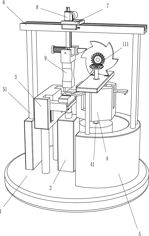
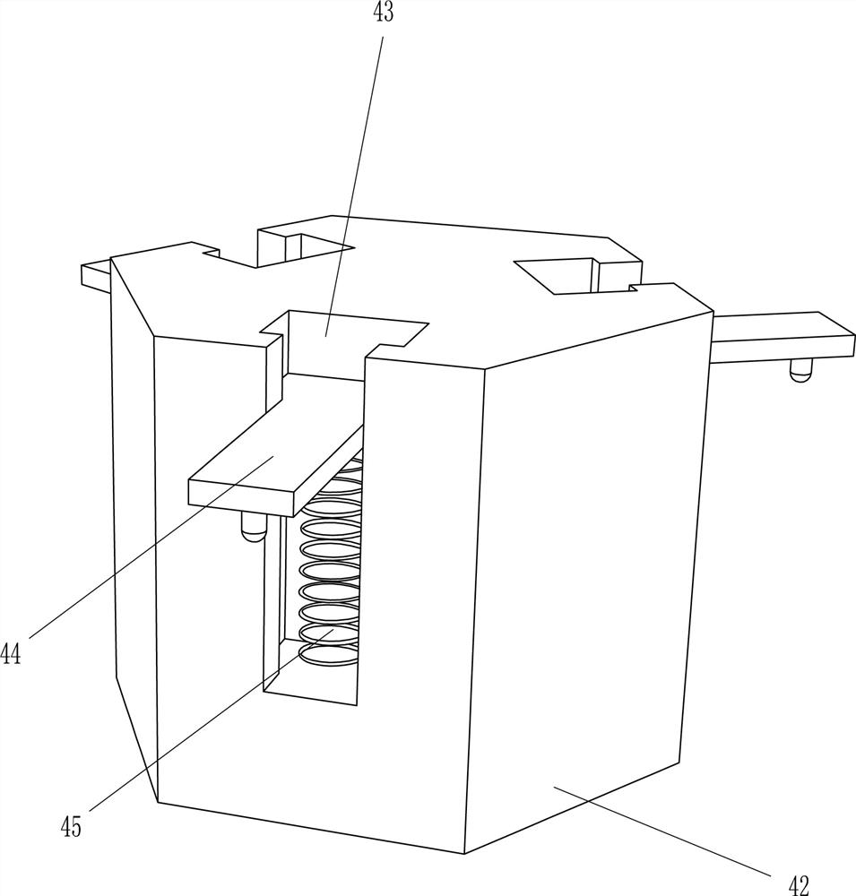
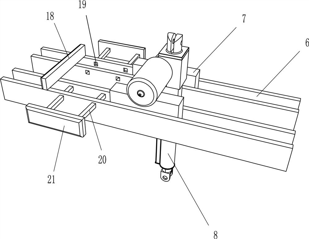
[0023] A hammer assembly device such as Figure 1-4 As shown, it includes a bottom plate 1, a placement cylinder 2, a clamping mechanism 3, an auxiliary nail placement mechanism 4, an arc seat 5, a bracket 51, a slide rail 6, a slider 7, a cylinder 8 and a hammer 9, and the top of the bottom plate 1 A placement tube 2 is arranged in the middle, a clamping mechanism 3 is provided on the left side of the top of the base plate 1, a nail auxiliary placement mechanism 4 is provided on the right side of the top base plate 1, an arc-shaped seat 5 is provided on the right side of the top of the base plate 1, and the top of the arc-shaped seat 5 and The left side of the top of the bottom plate 1 is provided with a bracket 51, two slide rails 6 are arranged on the two brackets 51, a slider 7 is slidably arranged on the slide rail 6, a cylinder 8 is arranged between the two sliders 7, and the telescopic rod of the cylinder 8 Percussion hammer 9 is arranged on.

[0024] The clamping mech...

Embodiment 2

[0028] On the basis of Example 1, such as figure 1 , 2 As shown in and 5, it also includes an N-shaped frame 10, a rotating shaft 11, a bevel gear 111, a hexagonal ratchet 12, a hexagonal block 13, a shrapnel 14, a guide sleeve 15, a wedge-shaped block 16 and a third elastic member 17, arc-shaped The top of the seat 5 is provided with an N-shaped frame 10, and the vertical direction is provided with a rotating shaft 11 in the middle of the top of the hexagonal column 42. The rotating shaft 11 passes through the N-shaped frame 10, and the N-shaped frame 10 is horizontally rotatable. 10. A hexagonal ratchet 12 and a hexagonal block 13 are arranged on the rotating shaft 11 in the horizontal direction. Bevel gears 111 are arranged on the two rotating shafts 11. The two bevel gears 111 mesh with each other. The top of the N-shaped frame 10 is symmetrically provided with shrapnel 14, shrapnel 14 In close contact with the two side walls of the hexagonal block 13, a guide sleeve 15 i...


PUM


Abstract

The invention belongs to the technical field of hammer assembling, particularly relates to a hammer assembling device, and aims to provide the hammer assembling device which can be automatically knocked and is high in safety. The hammer assembling device comprises a bottom plate, a clamping mechanism, an ail auxiliary placing mechanism, an arc-shaped seat, supports, sliding rails and an air cylinder; a placement barrel is arranged on the bottom plate; the clamping mechanism is arranged on one side, close to the placement barrel, of the bottom plate; the nail auxiliary placing mechanism is arranged on one side, away from the clamping mechanism, of the bottom plate; the arc-shaped seat is arranged on one side, close to the nail auxiliary placing mechanism, of the bottom plate; the supports are arranged on the top of the arc-shaped seat and one side, close to the clamping mechanism, of the bottom plate; the two sliding rails are arranged on the two supports, sliding blocks are arranged onthe two sliding rails in a sliding mode; and an air cylinder is arranged between the two sliding blocks. According to the hammer assembling device, the effects that automatic knocking can be achieved, and the safety is high are achieved.

Description

technical field [0001] The invention belongs to the technical field of hammer assembly, and in particular relates to a hammer assembly device. Background technique [0002] Most of the hammers are now assembled with wooden handles and hammer heads. The advantages of wooden handles are that they are simple to make and light to use, but wooden handles absorb moisture. As a result, the wooden handle and the hammer head are easily loosened, and the hammer may fall off from the wooden handle. Therefore, it is necessary to put a nail at the junction of the wooden handle and the hammer head for expansion and fixation. [0003] When assembling, the staff first puts the hammer head on the ground, then inserts the wooden handle into the mouth of the hammer head, then strikes the splicing, then reverses the hammer, and drives the nail into the wooden handle by tapping, so The staff has just completed the assembly work of the hammer. [0004] It can be seen from this that the manual a...

Claims


Application Information

Patent Timeline
IPC IPC(8): B25B27/02
CPCB25B27/026Y02P70/50
Inventor 胡嘉强
Owner 永康市德润有色金属有限公司
Why Eureka
Try Eureka