Bead punching equipment

A technology of punching equipment and rosary beads, which is applied in metal processing and other directions, can solve the problems of punching equipment that easily hurts hands, consumes manpower, and safety accidents, and achieves the effects of saving manpower, simple operation, and ensuring safety

Active Publication Date: 2020-10-16
肖辉
View PDF5 Cites 1 Cited by
  • Summary
  • Abstract
  • Description
  • Claims
  • Application Information

AI Technical Summary

Problems solved by technology

[0006] In order to overcome the shortcomings of the above-mentioned method, which is relatively labor-intensive in operation, and needs to be punched by hand-held rosary beads during operation, the punching equipment is easy to injure the hands and cause safety accidents due to misoperation. The technical problem to be solved by the present invention is Provide a rosary punching device that can save manpower and ensure the safety of operators during operation

Method used


Image

  • Bead punching equipment
  • Bead punching equipment
  • Bead punching equipment

Examples


Embodiment 1

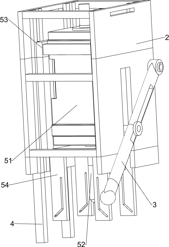
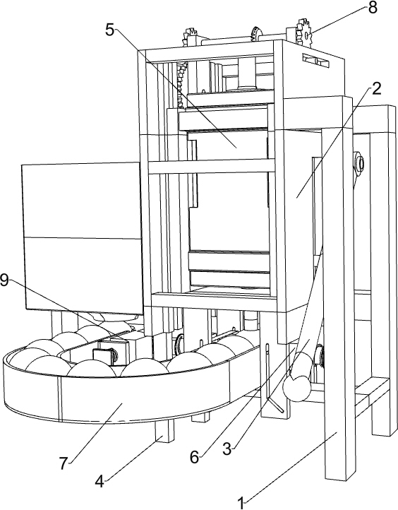
[0026] A rosary punching device such as Figure 1-5 As shown, it includes a right outrigger 1, a fixed frame 2, a rocker 3 and a left outrigger 4, the left side of the right outrigger 1 is connected with a fixed frame 2, and the fixed frame 2 is rotatably connected with a rocker 3, and the fixed frame 2 The left side is connected with a left supporting leg 4, and also includes a manual drilling assembly 5, a clamping assembly 6 and a manual feeding assembly 7, and a manual drilling assembly 5 is arranged between the fixed frame 2 and the rocking bar 3, and the left supporting leg 4 and A clamping assembly 6 and a manual feeding assembly 7 are arranged between the right legs 1 .

[0027] The manual drilling assembly 5 includes a biaxial motor 51, a drill bit 52, a motor mount 53 and a guide block 54, and the fixed frame 2 is slidably connected with a motor mount 53. Mounting seat 53 is slidably matched with rocking bar 3, drill bit 52 is connected on the output shaft of biaxia...

Embodiment 2

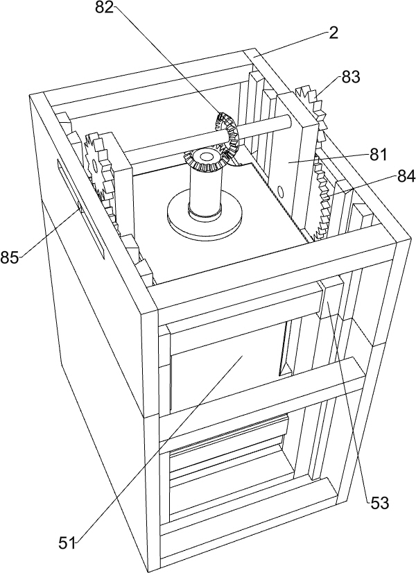
[0032] On the basis of Example 1, such as Figure 4 As shown, an automatic drilling assembly 8 is also included, and the automatic drilling assembly 8 includes a gear mounting plate 81, a bevel gear 82, a first cylindrical gear 83, a second cylindrical gear 84 and a clamping column 85, and the motor mounting seat 53 top left and right Both sides are connected with gear mounting plates 81, and the upper parts of the gear mounting plates 81 on both sides are connected with the first cylindrical gear 83 in a rotational manner, and the transmission shafts of the two first cylindrical gears 83 are connected to each other. Bevel gears 82 are connected to the output shaft above the biaxial motor 51, and the two bevel gears 82 are meshed with each other. The bottom of the gear mounting plate 81 on both sides is connected with a second cylindrical gear 84 in a rotational manner, and the second cylindrical gear 84 is connected to the first cylindrical gear. The cylindrical gear 83 meshe...


PUM


Abstract

The invention relates to punching equipment, in particular to bead punching equipment. The bead punching equipment can save manpower and ensure the safety of an operator during operation. The bead punching equipment comprises a right supporting leg, a rocking bar, a left supporting leg, a manual drilling assembly, a clamping assembly and a manual feeding assembly, wherein one side of the right supporting leg is connected with a fixed frame, the rocking bar is rotationally connected to the fixed frame, the left supporting leg is connected to one side of the fixed frame, the manual drilling assembly is arranged between the fixed frame and the rocking bar, the clamping assembly is arranged between the left supporting leg and the right supporting leg, and the manual feeding assembly is arranged between the left supporting leg and the right supporting leg. Through cooperative operation of the manual drilling assembly, the clamping assembly and the manual feeding assembly, a bead is punched,and therefore the effect of punching the bead is achieved.

Description

technical field [0001] The invention relates to a punching device, in particular to a rosary punching device. Background technique [0002] Rosary beads, also known as number beads, mainly refer to the items used by some religions in prayer, singing, chanting, mantra or spiritual practice, generally in traditional religions such as Taoism, Buddhism, Orthodox Church, Anglicanism, Islam, Hinduism, Sikhism and Baha'i teachings. Some rosary beads will be strung together before use, and then used, and before stringing rosary beads, it is necessary to punch the rosary beads. [0003] At present, the method of punching the rosary is usually to manually hold the rosary to align the punching device, and then push the rosary to punch the hole. The above method is more labor-intensive in operation, and it needs to be punched by the manual hand-held rosary during operation. , The punching equipment is easy to injure the hand due to misoperation, resulting in a safety accident. [000...

Claims


Application Information

Patent Timeline
IPC IPC(8): B26F1/16B26D5/06B26D5/02B26D5/08B26D7/02B26D7/06B26D7/26
CPCB26F1/16B26D5/06B26D5/02B26D5/086B26D7/02B26D7/0608B26D7/2628
Inventor 肖辉
Owner 肖辉
Why Eureka
Try Eureka