
Closestool forming and demolding device

A demoulding device and technology for molding molds, applied in unloading devices, ceramic molding machines, auxiliary molding equipment, etc., can solve the problems of low demoulding work efficiency, achieve low demoulding work efficiency, simple operation, and novel design Effect

Active Publication Date: 2020-10-16
GUANGDONG SUNCOO TECH
View PDF7 Cites 2 Cited by
  • Summary
  • Abstract
  • Description
  • Claims
  • Application Information

AI Technical Summary

Problems solved by technology

[0006] In view of the deficiencies of the above-mentioned prior art, the purpose of the present invention is to provide a toilet forming and demoulding device, which greatly reduces labor intensity and quickly completes the demoulding work of the toilet, aiming at solving the problem of low demoulding efficiency in the prior art

Method used


Image

  • Closestool forming and demolding device
  • Closestool forming and demolding device
  • Closestool forming and demolding device

Examples


Embodiment Construction

[0040] The present invention provides a toilet forming and demoulding device. In order to make the purpose, technical solution and effect of the present invention clearer and clearer, the present invention will be further described in detail below with reference to the accompanying drawings and examples. It should be understood that the specific embodiments described here are only used to explain the present invention, not to limit the present invention.

[0041] In describing the present invention, it is to be understood that the terms "left", "right", "upper", "lower", "front", "rear", "top", "bottom" etc. indicate an orientation or position The relationship is the orientation or position relationship of the present invention based on the drawings, and is only for the convenience of describing the present invention and simplifying the description. In addition, the terms "first" and "second" are used for descriptive purposes only, and cannot be understood as indicating or imp...


PUM


Abstract

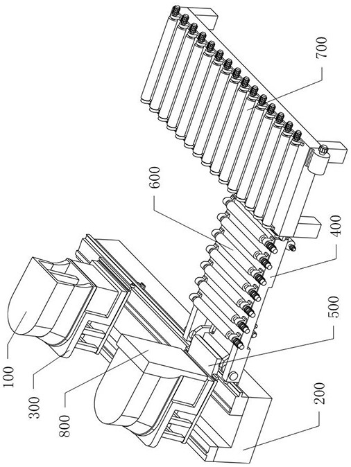
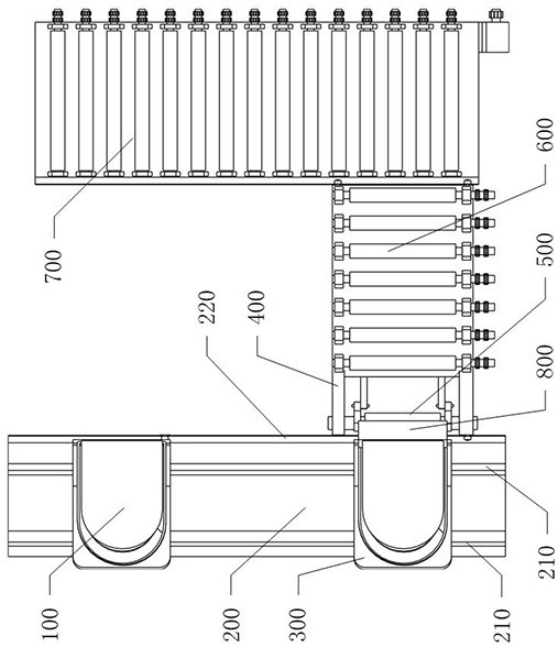
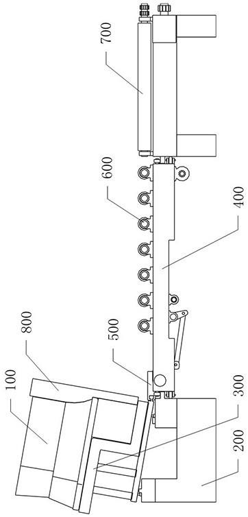
The invention provides a closestool forming and demolding device and belongs to the technical field of ceramic molding equipment. The device structurally comprises a base and a plurality of forming dies arranged on the base at intervals. Each forming die comprises a left auxiliary vehicle die, a main vehicle die, a right auxiliary vehicle die and a liftable upper die which are slidably connected to the base. The device further comprises a demolding support which can be matched and connected with the back of a closestool, a roller conveyor arranged on the right side of the base and a moving trolley which can move in the conveying direction of the roller conveyor. A conveying mechanism with a conveying plane flush with the roller conveyor is arranged on the top surface of the moving trolley.The moving trolley is provided with a turnover mechanism used for driving the main vehicle die to overturn to the conveying mechanism. According to the closestool forming and demolding device, the closestool and the demolding support on the main vehicle die are overturned to the conveying mechanism by the overturning mechanism, the closestool and the main vehicle die are separated under the conveying action of the conveying mechanism, the labor intensity is greatly reduced, the demolding work of the closestool is quickly completed, and the problem of low demolding efficiency in the prior artis solved.

Description

technical field [0001] The invention belongs to the technical field of ceramic forming equipment, and in particular relates to a toilet forming and demoulding device. Background technique [0002] The toilet is also called a toilet, which is divided into a direct flush type and a siphon type according to the flushing principle, and as a sanitary ware, it is widely used in cities and villages. Ceramic toilets on the market are basically composed of three parts: water tank, basin body, and shell. The following steps are required in the toilet manufacturing process: slurry preparation, glaze configuration, grouting molding, blank trimming, and blank inspection , glazing, kiln firing, inspection, packaging and delivery, etc. [0003] In the grouting molding process, the configured raw materials are injected into the molding mold to form the toilet body. For example, the utility model patent with the authorized notification number CN204471563U discloses a ceramic toilet pouring...

Claims


Application Information

Patent Timeline
IPC IPC(8): B28B1/26B28B17/00B28B13/06B28B7/46
CPCB28B1/26B28B1/261B28B7/46B28B13/065B28B17/0081
Inventor 霍晓新
Owner GUANGDONG SUNCOO TECH
Learn More