A quick cutting device for packaging production

A rapid cutting and packaging film technology, applied in packaging, transportation and packaging, paper/cardboard containers, etc., can solve the problems of increasing production costs, cutting blade damage, and destroying packaging bags, etc., to reduce incomplete cutting and increase production Efficiency and the effect of increasing production efficiency

Active Publication Date: 2021-12-07
TONGLING UNIV
View PDF12 Cites 0 Cited by
  • Summary
  • Abstract
  • Description
  • Claims
  • Application Information

AI Technical Summary

Problems solved by technology

[0003] 1. Most packaging bag cutting devices use a linear reciprocating mechanism to cut them. This cutting method is intermittent, that is to say, after cutting a packaging bag, it needs to stay for a short period of time before continuing to cut, which greatly reduces the production of enterprises. At the same time, this kind of equipment also needs to be equipped with a separate device to control the delivery and stop of packaging bags, which increases the production cost of the enterprise;
[0004] 2. The existing cutting device for bagged products presses the part to be cut into the knife groove through the cutting blade, and only relies on the downward pressure of the cutting blade to complete the cutting of the packaging bag. Since the packaging bag is not only to attract customers' attention, What is more important is to protect the product. Therefore, the packaging bag has good ductility and puncture resistance, and this cutting method makes many packaging bags not cut completely, and even destroys the packaging bag, increasing the rate of defective products , thereby affecting the production efficiency of the enterprise;
[0005] 3. At present, the cutting equipment of many packaging bags directly exposes the cutting blade to the outside world, which cannot provide good protection for the cutting blade, which greatly increases the probability of the cutting blade being damaged by external factors. It can cause personal injury, and there is a great potential safety hazard

Method used


Image

  • A quick cutting device for packaging production
  • A quick cutting device for packaging production
  • A quick cutting device for packaging production

Examples


Embodiment Construction

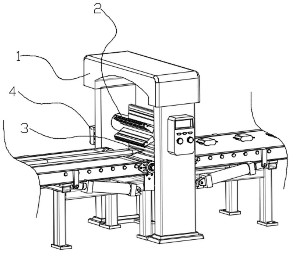
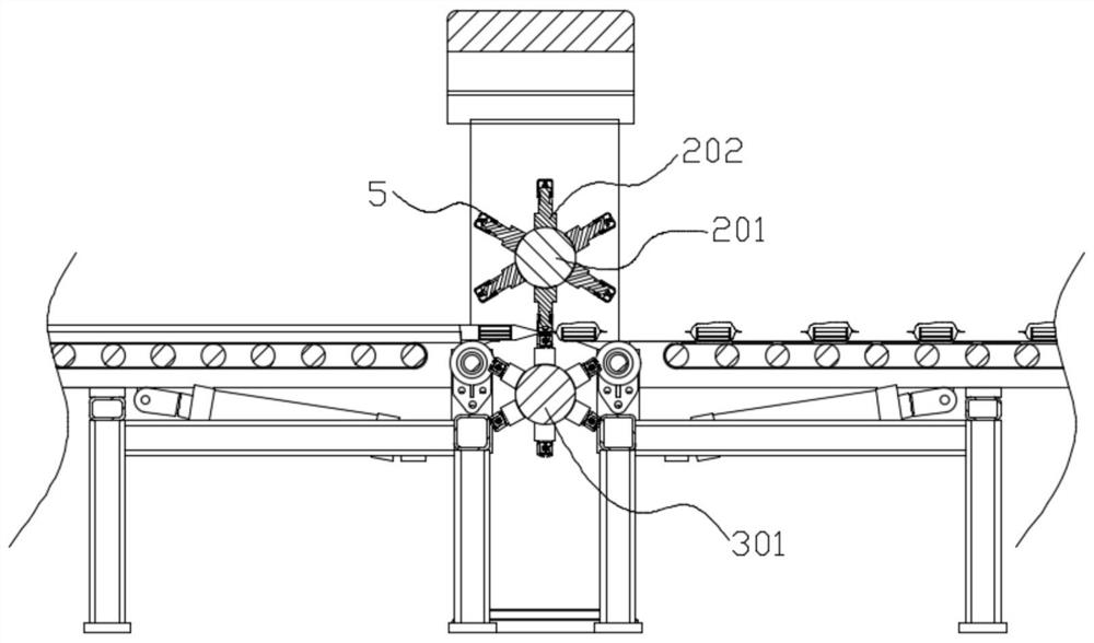
[0046] see figure 1 , in an embodiment of the present invention, a quick cutting device for packaging production, which includes: a frame 1, a cutting assembly 2 and a heating device 3, the cutting assembly 2 is rotatably connected to the middle of the frame 1, and is used to The drum packaging film of the product is cut into multiple independent packaging bags;

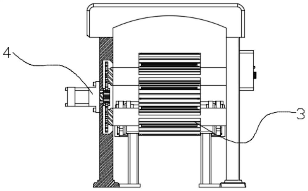
[0047] The heating device 3 is arranged directly below the cutting assembly 2 and is rotatably connected to the frame 1 for heating and sealing the packaging film before cutting;

[0048] The left and right sides of the frame 1 are provided with conveyor belts, the left side of the frame 1 is the feed end, the right end is the discharge end, and the two conveyor belts operate independently of each other;

[0049] The cutting assembly 2 and the heating device 3 are respectively arranged on the upper and lower sides of the conveyor belt, and are all driven by a driving motor 4 through gears. The rotation directions of...


PUM


Abstract

The invention discloses a quick cutting device for packaging production, which includes: a frame, a cutting assembly and a heating device, the cutting assembly is rotatably connected to the middle of the frame, and is used for cutting a drum packaging film containing products into multiple pieces. an independent packaging bag; the heating device is arranged directly below the cutting assembly, and is rotatably connected to the frame for heating and sealing the packaging film before cutting; the left and right sides of the frame are equipped with conveyor belts, and the The left side of the frame is the feed end, the right end is the discharge end, and the two conveyor belts operate independently of each other; the cutting assembly and the heating device are respectively arranged on the upper and lower sides of the conveyor belt, and are driven by a driving motor. Driven by gears, the rotation directions of the cutting assembly and the heating device are opposite, and the driving motor is installed at the rear of the frame.

Description

technical field [0001] The invention belongs to the technical field of cutting equipment, in particular to a quick cutting device for packaging production. Background technique [0002] In the process of product production, packaging plays a vital role. Therefore, enterprises have very strict standards for product packaging. At present, many factories have to save input costs while improving the packaging efficiency of bagged products. The work of bagging, sealing and cutting of products is carried out at the same time. Therefore, the speed of cutting also determines the efficiency of packaging. However, according to the investigation, it is found that the existing cutting devices for bagged products often have the following problems: [0003] 1. Most packaging bag cutting devices use a linear reciprocating mechanism to cut them. This cutting method is intermittent, that is to say, after cutting a packaging bag, it needs to stay for a short period of time before continuing t...

Claims


Application Information

Patent Timeline
Patent Type & Authority Patents(China)
IPC IPC(8): B31B70/00B31B70/10B31B70/14B31B70/16B31B70/64
CPCB31B70/006B31B70/10B31B70/146B31B70/16B31B70/645B31B70/649
Inventor 孔国庆王梦莹
Owner TONGLING UNIV
Why Eureka
Try Eureka