
Novel supercavitation airfoil profile hydrofoil craft

A supercavitation and hydrofoil technology, applied in the field of ships, can solve the problems of not meeting the working requirements of ships, affecting the aero-hydrodynamic performance of the hydrofoil, increasing the complexity of the mechanism, etc., and achieving simple structure, increasing working range, and reducing tail. The effect of edge eddy currents

Active Publication Date: 2020-10-16
INST OF MECHANICS - CHINESE ACAD OF SCI
View PDF11 Cites 2 Cited by
  • Summary
  • Abstract
  • Description
  • Claims
  • Application Information

AI Technical Summary

Problems solved by technology

However, when this scheme is applied to the existing common NACA hydrofoil structure, the increased cavitation at high speed will affect the aerohydrodynamic performance of the hydrofoil, and when applied to the existing supercavitating hydrofoil, it will The working efficiency at low speed will also be reduced, which cannot meet the working requirements of the ship at low speed
[0006] In addition, the technology of forming supercavitation through artificial ventilation requires the addition of additional ventilation devices, thereby increasing the complexity of the mechanism

Method used


Image

  • Novel supercavitation airfoil profile hydrofoil craft
  • Novel supercavitation airfoil profile hydrofoil craft
  • Novel supercavitation airfoil profile hydrofoil craft

Examples


Embodiment Construction

[0058] The specific structure and implementation process of this solution will be described in detail below through specific embodiments and accompanying drawings.

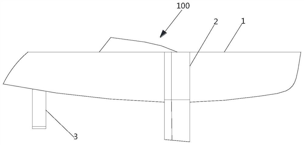
[0059] Such as figure 1 As shown, in one embodiment of the present invention, a hydrofoil boat 100 with a novel supercavitating airfoil is disclosed, which includes a ship main body 1, two symmetrical front hydrofoils 2 installed in the front section of the ship main body 1, and A tail hydrofoil 3 arranged at the stern.

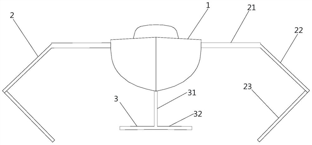
[0060] Such as figure 2 As shown, the front hydrofoil 2 includes a horizontal flat wing 21 connected in sequence, an inclined wing 22 connected to the end of the flat wing 21 away from the ship body 1 and inclined downward, and a folded wing connected to the inclined wing 22 and inclined toward the ship body 1. The wing 23 and the flat wing 21 are NACA airfoils, the oblique wing 22 and the folded wing 23 are new supercavitation airfoils; the angle between the oblique wing 22 and the folded win...


PUM


Abstract

The invention provides a novel supercavitation airfoil profile hydrofoil craft which comprises a ship main body, a front hydrofoil arranged at the front section of the ship main body and a tail hydrofoil arranged at the stern, and the front hydrofoil comprises a flat wing, a novel supercavitation wing type inclined wing and a folding wing which are connected in sequence; the tail hydrofoil comprises a vertically-installed NACA wing type vertical wing and a novel super-cavitation wing type short wing horizontally fixed to the lower end of the vertical wing. The novel supercavitation airfoil comprises a suction surface and a stress surface of which one ends are connected and the other ends are opened, and a contraction end connected with the opening end, and the suction surface, the stress surface and the contraction are respectively used for determining the outline by utilizing a numerical simulation method, a Johnson three-order design method and an NACA design method. According to thehydrofoil craft, the pneumatic-hydrodynamic integrated combined front hydrofoil with the novel super-cavitation airfoil and the deep-submerged empennage are adopted, so that the hydrofoil craft has good rapidity and stability during high-speed and low-speed sailing, and the effects of being high in working adaptability, simple in structure, reliable in working and capable of saving the manufacturing cost are achieved.

Description

technical field [0001] The invention relates to the field of ships, in particular to a hydrofoil ship which adopts a novel supercavitation airfoil to reduce wave resistance and viscous resistance during navigation. Background technique [0002] With the continuous consumption of land resources, countries around the world regard the utilization and development of marine resources as an important strategy for social development, which puts forward an urgent demand for the development of high-performance ships. The resistance of a ship is closely related to the speed of the ship. Most of the hulls of traditional ships are immersed below the water surface, and the wet surface area is large, which increases the resistance of navigation. The viscous resistance is approximately proportional to the square of the speed, and the wave resistance is approximately proportional to the speed The sixth power of , so the improvement of the speed of traditional ships is greatly restricted. ...

Claims


Application Information

Patent Timeline
IPC IPC(8): B63B1/24B63B1/26B63B1/38
CPCB63B1/248B63B1/26B63B1/38B63B2001/382Y02T70/10
Inventor 王一伟黄仁芳支玉昌杜特专王静竹黄晨光
Owner INST OF MECHANICS - CHINESE ACAD OF SCI
Learn More