
Carbon fiber warp knitting machine waste silk sucking device and use method

A warp knitting machine and carbon fiber technology, applied in textiles, papermaking, knitting, etc., can solve the problems of cumbersome operation, small capacity of the waste suction device, and inability to adjust the working frequency, so as to achieve the effect of improving the degree of automation

Inactive Publication Date: 2020-10-16
NEWTRY COMPOSITE
View PDF8 Cites 0 Cited by
  • Summary
  • Abstract
  • Description
  • Claims
  • Application Information

AI Technical Summary

Problems solved by technology

[0002] Carbon fiber warp knitting machines are equipped with a waste silk suction device to recycle the waste silk produced during the production process. However, the control methods of the existing waste silk suction devices are relatively simple, the working frequency cannot be adjusted, and the safety is difficult to guarantee.
[0003] The carbon fiber warp knitting machine waste suction device has a small capacity and relatively small suction; when collecting waste silk, it is necessary to manually open the waste suction device door, put the waste silk into a plastic bag and put it into a carton, and the operation is cumbersome; It is necessary to repeat the operation of collecting waste silk for a period of time, increasing the labor intensity of workers and reducing efficiency

Method used

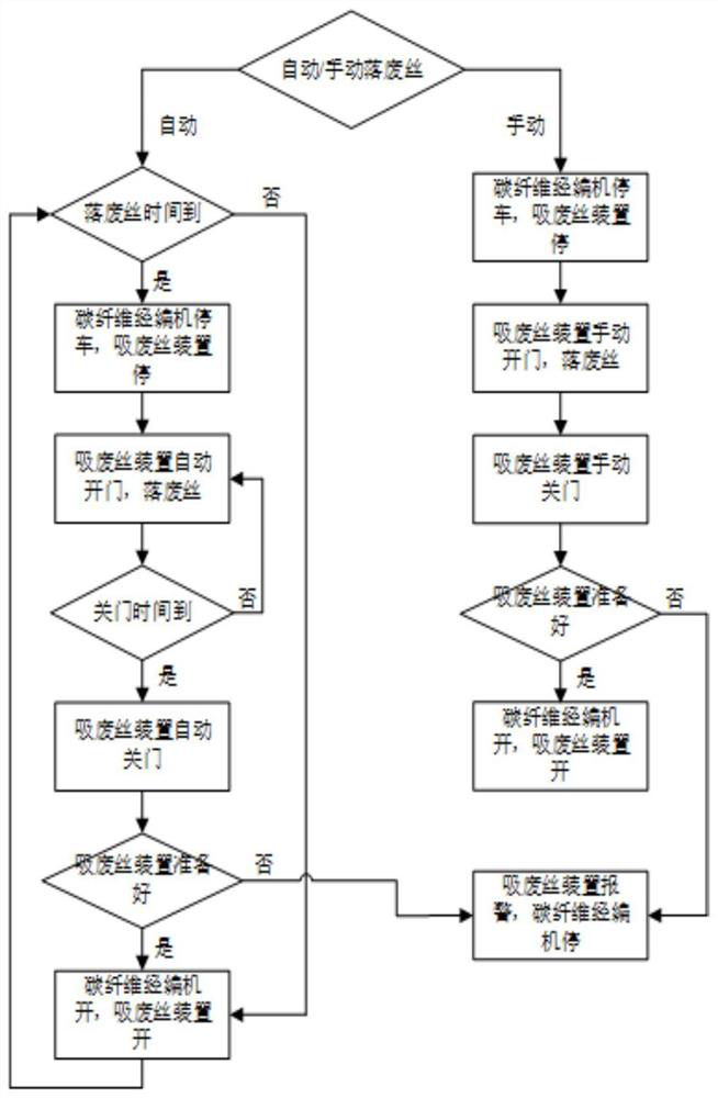
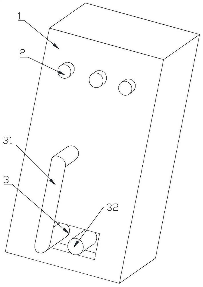
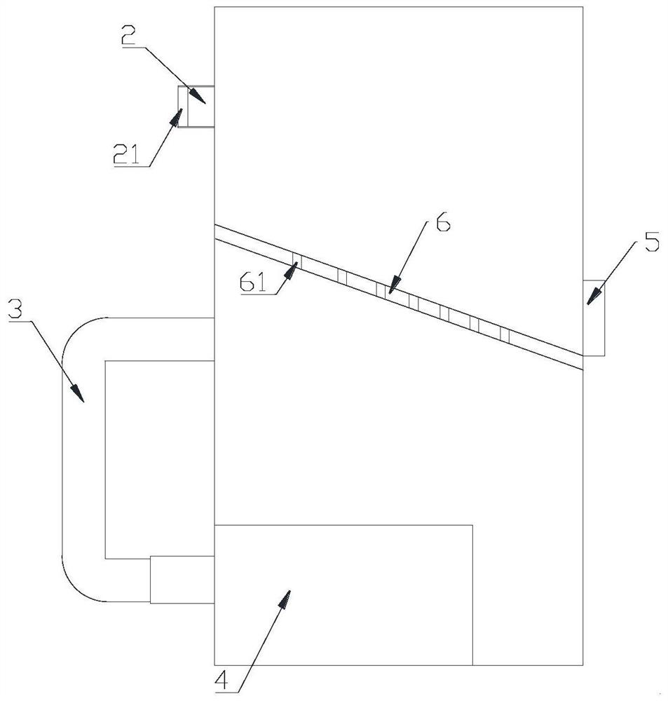

Image

  • Carbon fiber warp knitting machine waste silk sucking device and use method
  • Carbon fiber warp knitting machine waste silk sucking device and use method
  • Carbon fiber warp knitting machine waste silk sucking device and use method

Examples


Embodiment Construction

[0035] The following will clearly and completely describe the technical solutions in the embodiments of the present invention with reference to the accompanying drawings in the embodiments of the present invention. Obviously, the described embodiments are only some, not all, embodiments of the present invention.

[0036] In the description of the present invention, it should be noted that the terms belonging to "center", "upper", "lower", "left", "right", "vertical", "horizontal", "inner", "outer" etc. The indicated orientation or positional relationship is based on the orientation or positional relationship shown in the drawings, and is only for the convenience of describing the present invention and simplifying the description, rather than indicating or implying that the referred device or element must have a specific orientation, or in a specific orientation. construction and operation, therefore, should not be construed as limiting the invention.

[0037] A carbon fiber wa...


PUM


Abstract

The invention relates to the technical field of carbon fiber waste silk recycling, in particular to a carbon fiber warp knitting machine waste silk sucking device and a use method. The device comprises a housing main body, joints, a power mechanism, a discharge port and a sliding material plate. The housing main body is provided with a receiving cavity to store waste silk. A plurality of joints are arranged on the housing main body, and are connected with a waste silk output end of the carbon fiber warp knitting machine to receive the waste silk. The power mechanism is arranged in the housingmain body and provides suction for the joints to suck the waste wire in the receiving cavity. The discharge port is opened on the side of the housing main body and can be opened by a cap to communicate with the receiving cavity and take out the waste wire stored in the receiving cavity. The sliding material plate is obliquely arranged inside the shell body, and separates the receiving cavity fromthe power mechanism. The purpose of the device is to provide the carbon fiber warp knitting machine waste silk sucking device and the use method in response to the defects in the prior art, improve the automation of the device, and store and automatically slide the sucked waste silk out according to the situation. The device is extremely practical.

Description

technical field [0001] The invention relates to the technical field of recycling carbon fiber waste silk, in particular to a carbon fiber warp knitting machine waste suction device and a use method. Background technique [0002] Carbon fiber warp knitting machines are equipped with a waste silk suction device to recycle the waste silk produced during the production process. However, the control methods of the existing waste silk suction devices are relatively simple, the working frequency cannot be adjusted, and the safety is difficult to guarantee. . [0003] The carbon fiber warp knitting machine waste suction device has a small capacity and relatively small suction; when collecting waste silk, it is necessary to manually open the waste suction device door, put the waste silk into a plastic bag and put it into a carton, and the operation is cumbersome; The operation of collecting waste silk will be repeated for a period of time, increasing the labor intensity of workers a...

Claims


Application Information

Patent Timeline
IPC IPC(8): D04B35/32
CPCD04B35/32
Inventor 谈源徐万里刘勇俊徐鑫何小伟耿平康
Owner NEWTRY COMPOSITE
Learn More