Building wall space spraying device
A spraying device and technology for construction, applied in the field of building decoration, can solve the problems of affecting the efficiency of spraying, human fatigue, time-consuming and laborious, etc., and achieve the effect of improving functionality and good practicability
- Summary
- Abstract
- Description
- Claims
- Application Information
AI Technical Summary
Problems solved by technology
Method used
Image

Examples
Embodiment 1
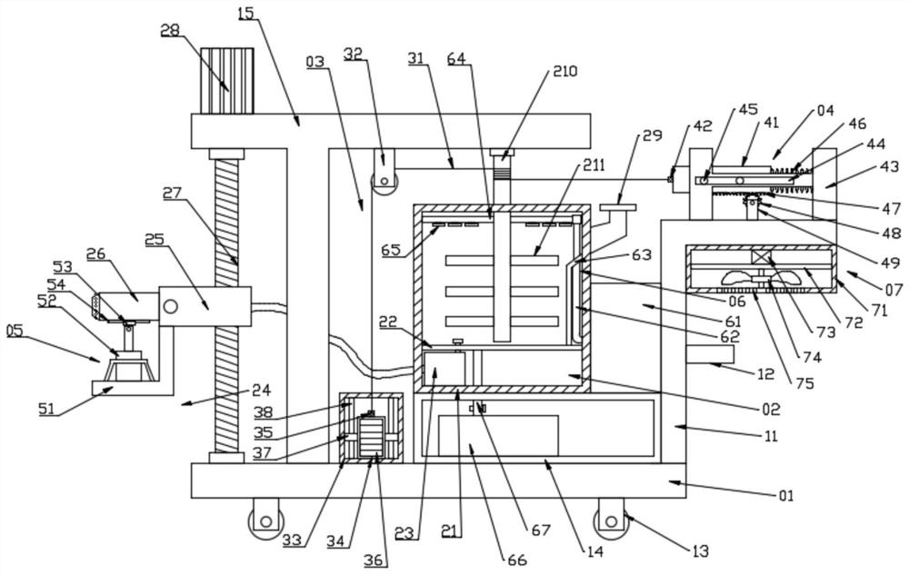
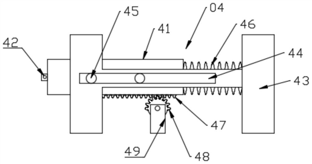
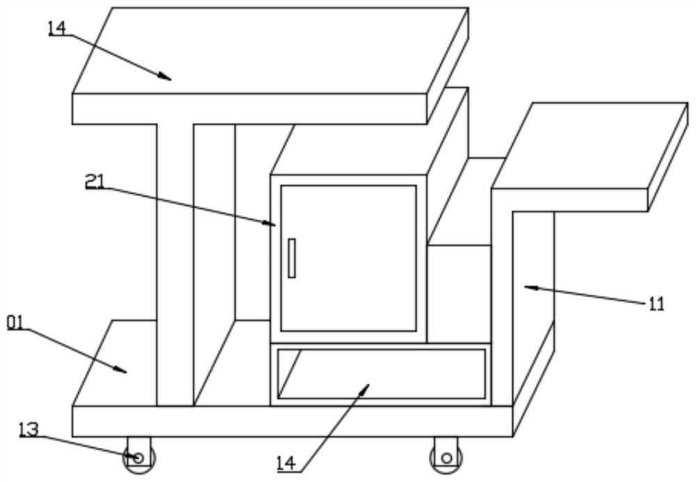
[0024] see Figure 1~3 , in an embodiment of the present invention, a construction wall spraying device includes a support base 01, a first frame body 11 is fixed on the support base 01, a push handle 12 is provided on the first frame body 11, and the push handle 12 is used to facilitate driving The whole is moved; the support base 01 is fixed with a support base 14, and the support base 14 is provided with a spraying assembly 02 and a cleaning assembly 06, and the wall surface can be sprayed through the spraying assembly 02, which is very simple; the support base 14 is a There is a lifting component 03 on the side. The lifting component 03 is connected with the connecting rod 210 in the spraying component 02. The lifting component 03 can drive the connecting rod 210 to rotate, which is convenient for stirring. The lifting component 03 is connected with the driving component 04 on the push handle 12. , the lifting component 03 can be driven to work through the driving componen...
Embodiment 2
[0035] The bottom of the first spray head 26 is provided with an adjustment assembly 05, and the spraying angle of the first spray head 26 can be adjusted by the adjustment assembly 05; the bottom of the first spray head 26 is fixed with a slide rail 54, and the slide rail 54 is slidably connected with a second Slide block 53, the second slide block 53 is hinged with the output end of telescopic cylinder 52, and telescopic cylinder 52 is fixed on the protective frame 51, can drive second slide block 53 to slide on slide rail 54 when telescopic cylinder 52 works, and then adjusts The angle of the first spray head 26.
[0036] The working principle of the present invention is: the paint is introduced into the mixing tank 21 through the feed port 29, the paint is transferred to the first spray nozzle 26 by the discharge pump 23 for spraying, and the angle of spraying is adjusted by the adjustment assembly 05; during the spraying process The connecting rod 210 is driven to rotate ...
PUM
 Abstract
Description
Claims
Application Information