
Improved I-shaped aluminum connecting structure for aluminum alloy building

A connection structure, I-shaped aluminum technology, applied in the direction of connection components, rod connection, mechanical equipment, etc., can solve the problems of complex manufacturing process of three-dimensional connection plate, troublesome construction and installation, etc., to improve building construction efficiency, strengthen resistance strength, The effect of environmental safety

Pending Publication Date: 2020-10-16
ALUHOUSE TECHGD CO LTD
View PDF0 Cites 1 Cited by
  • Summary
  • Abstract
  • Description
  • Claims
  • Application Information

AI Technical Summary

Problems solved by technology

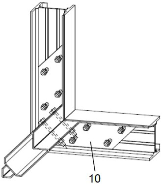
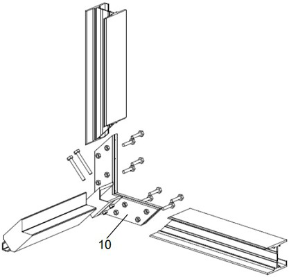
[0004] figure 1 and figure 2 Although the I-shaped aluminum connection structure shown has extremely strong stability and compression performance, it can transmit bending moment, which is beneficial to resist lateral force, reduces the use of column and beam connection parts, reduces manufacturing costs, and solves the problem of X , Y, and Z-axis components are installed in one piece, but the manufacturing process of the three-dimensional connecting plate is still relatively complicated. Due to the large number of workpieces, the construction and installation are also troublesome.

Method used


Image

  • Improved I-shaped aluminum connecting structure for aluminum alloy building
  • Improved I-shaped aluminum connecting structure for aluminum alloy building
  • Improved I-shaped aluminum connecting structure for aluminum alloy building

Examples


Embodiment Construction

[0034] The present invention will be described in detail below in conjunction with the accompanying drawings and embodiments.

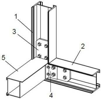
[0035] see Figure 3 to Figure 6 , the present invention provides an improved aluminum alloy building I-shaped aluminum connection structure, which is mainly composed of two or more I-shaped aluminum components, a triangular connecting plate 3, an overlapping plate 4, a bottom beam 5 and a fixed connecting piece, wherein the I-shaped aluminum There are a first I-shaped aluminum component 1 and a second I-shaped aluminum component 2 in the shaped aluminum component.

[0036] Such as image 3 and Figure 4 As shown, the vertical lower end of the first I-shaped aluminum member 1 has an oblique cut as the connection end, and the horizontal inner end of the second I-shaped aluminum member 2 has an oblique cut as the connection end.

[0037] The triangular connecting plate 3 is provided with an upwardly extending connecting portion and a laterally extend...


PUM


Abstract

The invention relates to an improved I-shaped aluminum connecting structure for an aluminum alloy building. The improved I-shaped aluminum connecting structure for the aluminum alloy building comprises two or more I-shaped aluminum components, triangular connecting plates, lap joint plates, a bottom cross beam and fixed connecting pieces. The angular lap joint plates are fixedly installed on the planes, close to the roots of connecting parts, of the triangular connecting plates. The upward connecting parts of the triangular connecting plates are inserted into an I-shaped aluminum groove from the notch connecting end of the first I-shaped aluminum component to be fixed. The transverse connecting parts of the triangular connecting plates are inserted into an I-shaped aluminum groove from thenotch connecting end of the second I-shaped aluminum component to be fixed, so that the triangular connecting plates are spliced into an angle shape and then laterally inserted into the bottom crossbeam. Long bolts are inserted into side plate screw holes of the first I-shaped aluminum component, plate wall screw holes of the bottom cross beam and connecting plate screw holes in the other ends of the lap joint plates to be fixed. Integral installation of the components in the X-axis direction, the Y-axis direction and the Z-axis direction is achieved, two-dimensional connection and three-dimensional connection of the I-shaped aluminum components are achieved, and extremely high stability is achieved.

Description

technical field [0001] The invention belongs to the field of building construction, and in particular relates to an improved aluminum alloy construction I-shaped aluminum connection structure. Background technique [0002] In the practical application of aluminum alloy houses, wind load is the most important load of light buildings such as aluminum alloy houses. In areas with high wind pressure, the wind pressure acts on the roof and walls to form lateral forces, which have a greater impact on the force of the building structure. The conventional solution is to add oblique supports to the structure to enhance the structural resistance strength, but the increase of oblique supports makes it difficult to use prefabricated pipelines and pipelines between structural columns, which reduces the space utilization rate and reduces the efficiency of fabrication and installation. [0003] There is an I-shaped aluminum connection structure design for an aluminum alloy room, in which t...

Claims


Application Information

Patent Timeline
IPC IPC(8): F16B7/08F16B7/18
CPCF16B7/00F16B7/18
Inventor 邝海峰
Owner ALUHOUSE TECHGD CO LTD
Learn More