Sinusoidal force system friction testing method

A technology of system friction force and test method, applied in the field of control, can solve the problems of inaccurate test, modeling error, poor constant speed accuracy, etc., and achieve the effect of large amount of data information, high efficiency, and short test process time

Inactive Publication Date: 2020-10-16
BEIJING INFORMATION SCI & TECH UNIV
View PDF3 Cites 0 Cited by
  • Summary
  • Abstract
  • Description
  • Claims
  • Application Information

AI Technical Summary

Problems solved by technology

[0008] In view of this, the present invention provides a sinusoidal force system friction test method, which solves the problems of poor accuracy of constant speed, inaccurate testing and errors in modeling in the traditional technology

Method used


Image

  • Sinusoidal force system friction testing method
  • Sinusoidal force system friction testing method
  • Sinusoidal force system friction testing method

Examples


Embodiment 1

[0036] Embodiment 1: For testing linear motors

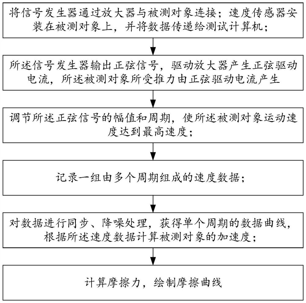
[0037] Step 1: Prepare the drive amplifier and set it in current mode; use the ARS2000 driver and set it to current drive mode through software.

[0038] Step 2: Connect the data generator, data collector, drive amplifier, and the system under test. Use PC and dSPACE DS1104 board to form data output and input system, use MATLAB software to design sinusoidal drive signal, input and output channel accessories system. Connect the analog output of DS1104 to the driver, connect the driver to the BOB-DTL85 linear motor, and connect the motor sensor to the DS1104 pulse interface.

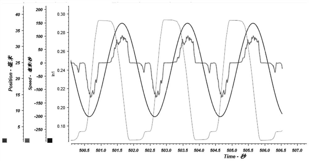
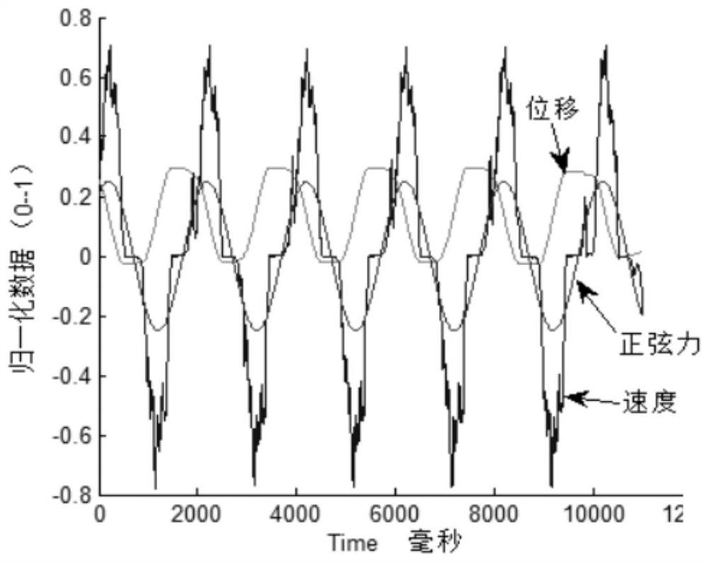
[0039] Step 3: output sinusoidal signal, drive amplifier to generate sinusoidal drive current, motor thrust F=ρAsin(ωt), ρ is thrust-current coefficient, fixed constant. Make the motor do reciprocating motion under the drive of sinusoidal force. Use Controdesk test software software to adjust the amplitude A and frequency ω of the signal. Generally, the ...

Embodiment 2

[0046] Embodiment 2: for rotating electric machine

[0047] The first step: same as embodiment one

[0048] Step 2: Connect the data generator, data collector, drive amplifier, and the system under test. Use PC and dSPACE DS1104 board to form data output and input system, use MATLAB software to design sinusoidal drive signal, input and output channel accessories system. Connect the analog output of DS1104 to the driver, connect the driver to the Kollmorgen AKM42G three-phase rotating motor, and connect the motor sensor to the DS1104 pulse interface.

[0049] The third step to the eighth step: with embodiment one;

Embodiment 3

[0050] Embodiment three: used for testing the torque motor.

[0051] The first step: same as embodiment one

[0052] Step 2: Connect the data generator, data collector, drive amplifier, and the system under test. Use PC and dSPACE DS1104 board to form data output and input system, use MATLAB software to design sinusoidal drive signal, input and output channel accessories system. Connect the analog output of DS1104 to the driver, connect the driver to the Yaskawa SGMCS-08D direct drive motor, and connect the motor sensor to the DS1104 pulse interface.

[0053] The third step to the eighth step: the same as embodiment one.


PUM


Abstract

The invention discloses a sinusoidal force system friction testing method. A signal generator is connected with a tested object through an amplifier; a speed sensor is installed on the tested object and transmits data to a test computer. The signal generator outputs a sinusoidal signal to drive the amplifier to generate a sinusoidal driving current, the thrust borne by the measured object is F = rho Asin (omega t), and rho is a thrust-current coefficient and is a constant; the amplitude and the period of the sinusoidal signal are adjusted to enable the moving speed of the measured object to reach the highest speed Vmax; a group of speed data V (t) composed of a plurality of periods are recorded; synchronization and noise reduction processing is performed on the data to obtain a data curveof a single period, and the acceleration a (t) of the measured object is calculated according to the speed data; the friction force is calculated according to f (t) = F (t)-Ma (t); and a friction curve is drawn according to the speed data V (t) and the friction data f (t). According to the sinusoidal force system friction testing method, the problems in the prior art that constant speed and low speed precision is poor, reversing friction cannot be tested, and discrete data feature points omit modeling errors can be solved.

Description

technical field [0001] The invention relates to the technical field of control, and more specifically relates to a method for testing friction of a sinusoidal force system. Background technique [0002] The causes of friction are more complex, and there are many factors that combine to form the overall friction. There are also a variety of analytical friction models established by researchers, such as Lugre and GSM models. Because of the large differences in mechanical characteristics that appear with changes in the application environment, it is inevitable to lose sight of the other when using a unified analytical model in practical applications; Moreover, the formation of friction causes is still being explored in recent research literature, which is even inconsistent with traditional conclusions. There are inherent shortcomings in the application of analytical models in complex environments. In practical applications, there is a certain degree of randomness in the main ...

Claims


Application Information

Patent Timeline
Patent Type & Authority Applications(China)
IPC IPC(8): G01L5/00
CPCG01L5/0028
Inventor 侯明付兴建李擎柏森
Owner BEIJING INFORMATION SCI & TECH UNIV
Why Eureka
Try Eureka