
Acceleration sensor assembly and acceleration sensor mounting method

A technology of acceleration sensor and installation method, which is applied in the field of sensors, can solve the problems that the thread glue cannot meet, affect the performance of the acceleration sensor, and the thread glue cannot meet the reliability requirements, etc., and achieve the effect of stable and reliable measurement data

Pending Publication Date: 2020-10-16
深圳市海纳微传感器技术有限公司
View PDF0 Cites 4 Cited by
  • Summary
  • Abstract
  • Description
  • Claims
  • Application Information

AI Technical Summary

Problems solved by technology

However, when the acceleration sensor is installed in a specific vibration environment, the thread glue cannot meet the reliability requirements; the working principle of the anti-loosening gasket is usually to use elastic deformation to generate pressure, and then increase friction to prevent loosening. However, through the test Verify that the elastic deformation produced in this way will directly affect the performance of the acceleration sensor
[0003] Therefore, in view of the technical problem that the thread glue in the above-mentioned prior art cannot meet the requirements of the stability and reliability of the acceleration sensor installed in the vibration environment, and the anti-loosening gasket directly affects the performance of the acceleration sensor, it is necessary to conduct research and development to provide a solution , to achieve a stable installation of the acceleration sensor

Method used


Image

  • Acceleration sensor assembly and acceleration sensor mounting method
  • Acceleration sensor assembly and acceleration sensor mounting method
  • Acceleration sensor assembly and acceleration sensor mounting method

Examples


Embodiment Construction

[0031] In order to make the technical problems, technical solutions and beneficial effects to be solved by the embodiments of the present invention clearer, the present invention will be further described in detail below in conjunction with the accompanying drawings and embodiments. It should be understood that the specific embodiments described here are only used to explain the present invention, not to limit the present invention.

[0032] It should be noted that when an element is referred to as being “fixed” or “disposed on” another element, it may be directly on the other element or be indirectly on the other element. When an element is referred to as being "connected to" another element, it can be directly connected to the other element or indirectly connected to the other element. In addition, the connection can be used for both fixing and circuit communication.

[0033] It is to be understood that the terms "length", "width", "top", "bottom", "front", "rear", "left", ...


PUM


Abstract

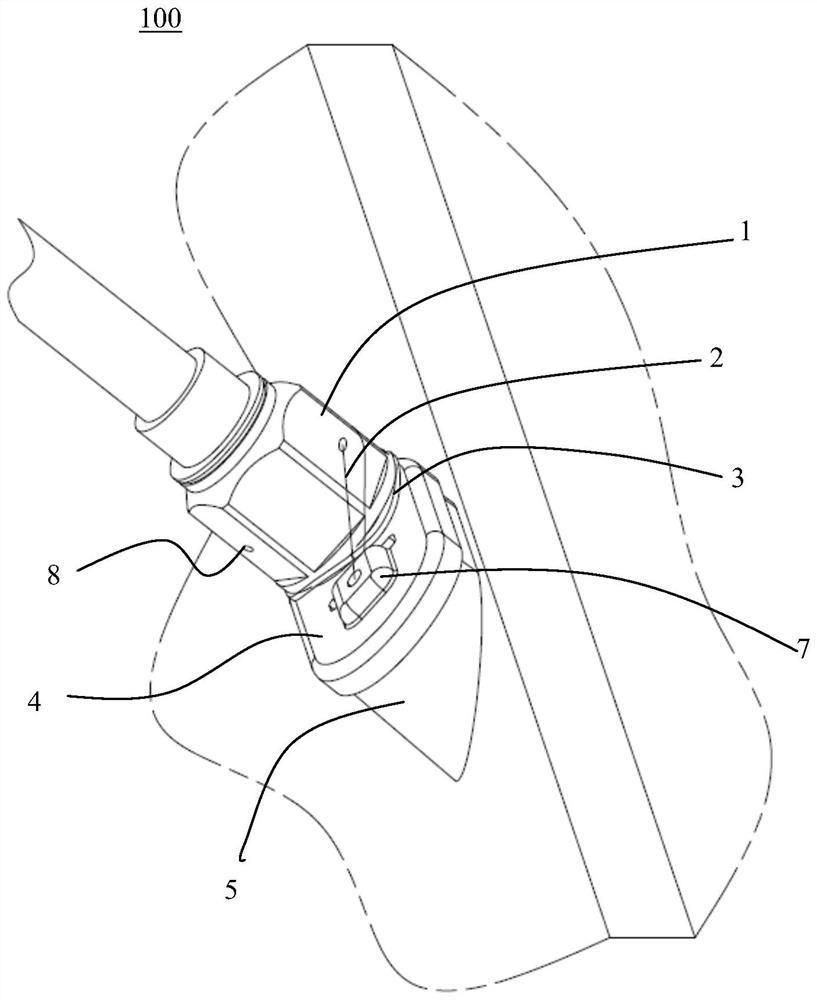
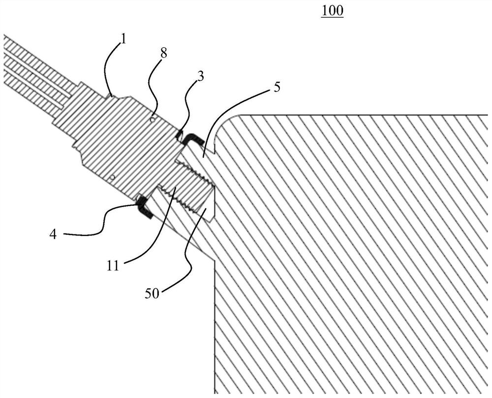
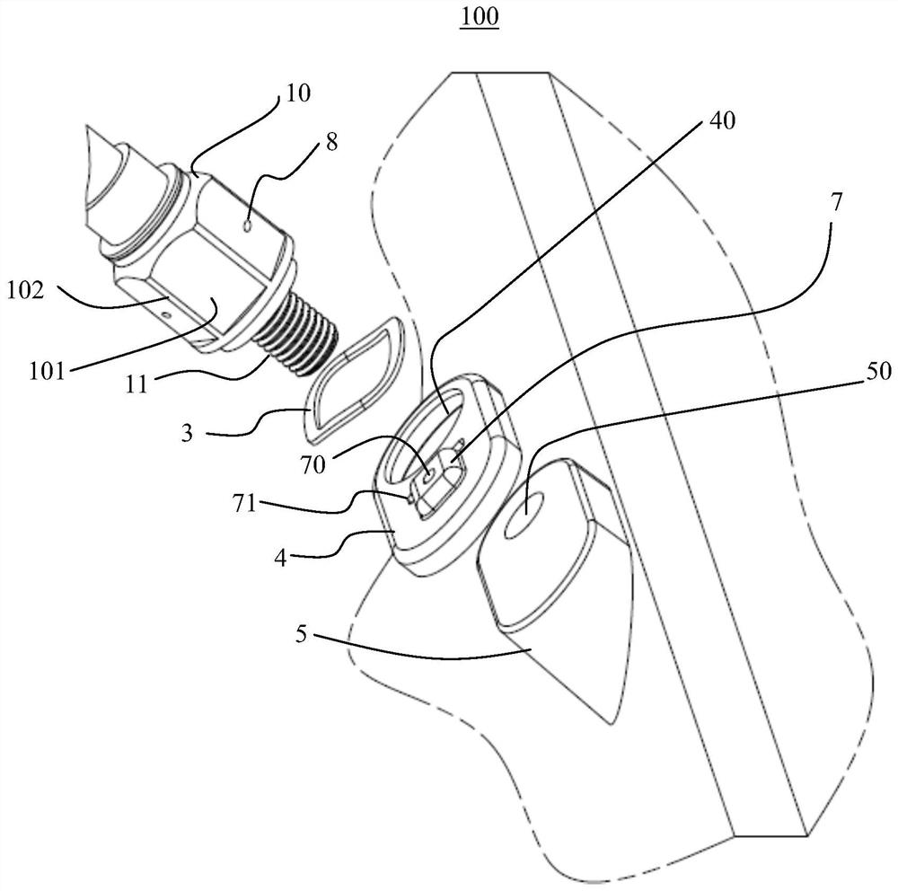
The invention discloses an acceleration sensor assembly and an acceleration sensor mounting method. The acceleration sensor assembly comprises an acceleration sensor, a steel wire, a waveform gasket,a special-shaped gasket and an installation boss. The acceleration sensor comprises a main body part, a shell coating the main body part, and a mounting bolt. At least one set of through holes are formed in the shell, and a steel wire fixing mechanism is arranged on the special-shaped gasket. The installation boss is provided with a threaded hole matched with the installation bolt and an installation face matched with the special-shaped gasket. The locking steel wire is fixed through the special-shaped gasket and the steel wire fixing hole, and when the acceleration sensor is screwed down, thespecial-shaped gasket is buffered and pressed through the elastic waveform gasket, so that the steel wire can be locked, looseness prevention of the sensor is achieved, and stable and reliable measurement data are obtained.

Description

technical field [0001] The invention relates to the technical field of sensors, in particular to an acceleration sensor component and an acceleration sensor installation method. Background technique [0002] Piezoelectric acceleration sensors are widely used in industrial monitoring, transportation, test and measurement and other fields, and have the characteristics of good reliability, high signal-to-noise ratio, and good frequency response. The piezoelectric acceleration sensor uses the piezoelectric effect of the crystal to complete the vibration measurement. When the measured body vibrates, it is transmitted to the sensor. The inertial mass Mass will generate pressure on the crystal Crystal, and the crystal element will generate charges. The charge is passed through the Charge converter. Converted into corresponding vibration parameters, so as to realize the measurement of vibration acceleration. In order to ensure the stable and reliable performance of the acceleration...

Claims


Application Information

Patent Timeline
Patent Type & Authority Applications(China)
IPC IPC(8): G01P15/09G01P15/08G01P1/02G01P1/00G01H11/08
CPCG01P15/09G01P15/0802G01P1/023G01P1/00G01H11/08
Inventor 赵杰倪玉涛
Owner 深圳市海纳微传感器技术有限公司
Learn More