Locking positioning structure

A locking positioning and nut technology, applied in the direction of locking fasteners, connecting members, threaded fasteners, etc., can solve problems such as jamming, limitations of applicability and practicability, and difficult-to-lock structures, and achieve structural settings. Reasonable, improve the fixed effect, and ensure the effect of stability

Active Publication Date: 2020-07-17
林义
View PDF19 Cites 1 Cited by
  • Summary
  • Abstract
  • Description
  • Claims
  • Application Information

AI Technical Summary

Problems solved by technology

However, nuts in harsh environments
[0003] (For example, the car is bumpy for a long time) After using it for a long time, the mechanical properties will attenuate, resulting in a decrease in the tightening force of the nut, or even loosening
[0004] Chinese patent 201810534002.7 discloses a locking structure assembly, which has a locking structure between the nut and the part to be locked, and a locking groove is fixed on the surface of the nut, and there are locking parts and locking parts on the locking structure. The locking part, when in use, the locking groove of the nut is engaged with the locking part. Although it can realize the locking function to a certain extent, in the actual use process, since the nut and the locking part are both steel sheets, the It is difficult to snap the locking structure into the card slot during normal application, and even if it can be snapped, the nut is prone to loosening due to bumps during long-term use, so it is difficult to meet the actual application and applicability and practicality is limited

Method used


Image

  • Locking positioning structure
  • Locking positioning structure

Examples


Embodiment 1

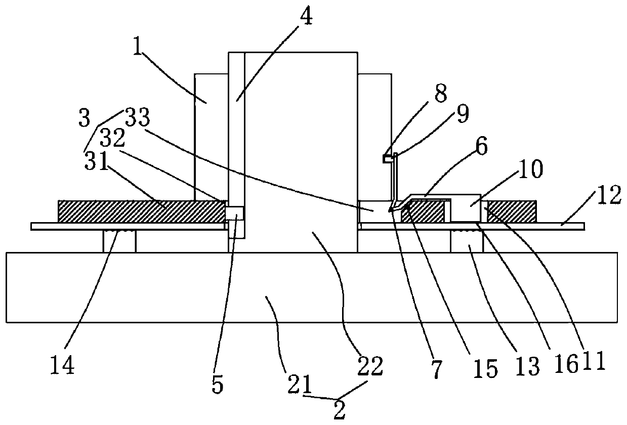
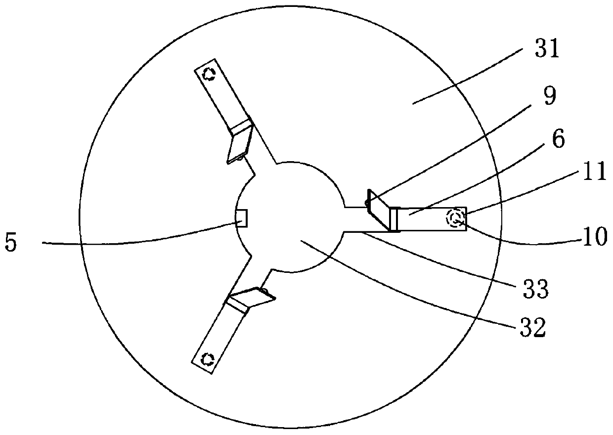
[0018] figure 1 and figure 2 A specific embodiment of the invention is shown in which figure 1 It is a structural schematic diagram of the present invention; figure 2 It is a specific structural schematic diagram of the locking structure of the present invention.

[0019] See figure 1 and figure 2 , a locking and positioning structure, including a bolt 2 and a nut 1, the bolt 2 includes a stud 21 and a nut 22, and a locking structure 3 is also provided between the nut 1 and the nut 22, so The locking structure 3 includes a backing plate 31, a circular hole 32 with the same diameter as the stud is opened in the center of the backing plate, and at least three grooves 33 are uniformly opened on the inner ring of the backing plate, The depth of the groove is the same as the thickness of the nut, and a vertical clamping groove 4 is provided on the side wall of the stud, and the vertical clamping groove 4 is integrally formed on the inner ring of the backing plate. The posi...


PUM


Abstract

The invention discloses a locking positioning structure. A bolt and a nut are included. The bolt comprises a stud and a screw cap. A locking structure is further arranged between the nut and the screwcap and comprises a cushion plate. The center of the cushion plate is provided with a circular hole with the diameter equal to the diameter of the stud. The inner ring of the cushion plate is evenlyprovided with at least three grooves. The side wall of the stud is provided with one vertical clamp groove. A positioning protrusion clamped into the vertical clamp groove is integrally formed on theinner ring of the cushion plate. V-shaped abutting blocks are further arranged. The corner positions of the V-shaped abutting blocks are connected in the grooves through pin shafts. Buckle grooves areevenly formed in the outer surface of the nut. Buckle protrusions are fixed to the top ends of the V-shaped abutting blocks. Abutting columns are fixed to the bottom ends of the V-shaped abutting blocks. The locking positioning structure is reasonable in structure arrangement, nut loosening preventing can be effectively achieved, the abutting columns can firmly abut against the top face of a to-be-locked piece, normal overhauling and maintaining of the nut cannot be influenced, locking stability is guaranteed, and applicability and practicability are high.

Description

technical field [0001] The invention belongs to the technical field of auto parts, and in particular relates to a locking and positioning structure. Background technique [0002] At present, when automobiles are assembled, many parts are locked and fixed by nuts. However, nuts in harsh environments [0003] (For example, when the car is bumpy for a long time) After a long time of use, the mechanical properties will attenuate, resulting in a decrease in the tightening force of the nut, or even loosening. [0004] Chinese patent 201810534002.7 discloses a locking structure assembly, which has a locking structure between the nut and the part to be locked, and a locking groove is fixed on the surface of the nut, and there are locking parts and locking parts on the locking structure. The locking part, when in use, the locking groove of the nut is engaged with the locking part. Although it can realize the locking function to a certain extent, in the actual use process, since the...

Claims


Application Information

Patent Timeline
IPC IPC(8): F16B39/10F16B39/24
CPCF16B39/108F16B39/24
Inventor 林义
Owner 林义
Why Eureka
Try Eureka