Cable insulation damage detection device

A damage detection and cable insulation technology, which is applied to measuring devices, measuring electricity, measuring electrical variables, etc.

Inactive Publication Date: 2020-10-16
匠桥智谷科技(涡阳)有限公司
View PDF0 Cites 2 Cited by
  • Summary
  • Abstract
  • Description
  • Claims
  • Application Information

AI Technical Summary

Problems solved by technology

[0002] A cable usually includes a cable core and an insulating sheath, and the insulation of the cable is extremely important for the safe use of the cable. On the one hand, in the production process of the cable, the insulation layer of the cable needs to be strictly tested to ensure compliance with the use standards. On the other hand, since the long-term use of the cable will affect the insulation effect of the cable to cause insulation damage, which may easily cause serious leakage or electric shock accidents, it is necessary to regularly detect the cable insulation damage, and the existing cable insulation detection device , most of the cables are detected by manually moving the detection probe. For longer cable detection, it is obviously time-consuming and laborious, which affects the efficiency of the staff for cable insulation detection. In addition, the existing detection methods need to power on the cable during the detection process. Therefore, the leakage is detected by the metal probe, so that there are potential safety hazards in the detection, and this detection method can only detect the breakdown of the insulation layer to cause leakage, and the insulation damage of the cable in actual use also includes the insulation layer. Hole damage, fine grain cracks, and softening and embrittlement caused by aging and heating. Although this kind of insulation damage does not cause direct leakage, it has obviously caused irreversible damage to the insulation layer of the cable, which will lead to electrical performance and mechanical failure of the insulation layer. Performance degradation, so there is also a great hidden danger of safe use, which needs to be repaired in time

Method used


Image

  • Cable insulation damage detection device
  • Cable insulation damage detection device
  • Cable insulation damage detection device

Examples


Embodiment Construction

[0034] In order to make the purpose, technical solutions and advantages of the present disclosure clearer, the present disclosure will be further described in detail below in conjunction with specific embodiments.

[0035] It should be noted that, unless otherwise defined, the technical terms or scientific terms used in one or more embodiments of the present specification shall have ordinary meanings understood by those skilled in the art to which the present disclosure belongs. "First", "second" and similar words used in one or more embodiments of the present specification do not indicate any order, quantity or importance, but are only used to distinguish different components. "Comprising" or "comprising" and similar words mean that the elements or items appearing before the word include the elements or items listed after the word and their equivalents, without excluding other elements or items. Words such as "connected" or "connected" are not limited to physical or mechanica...


PUM


Abstract

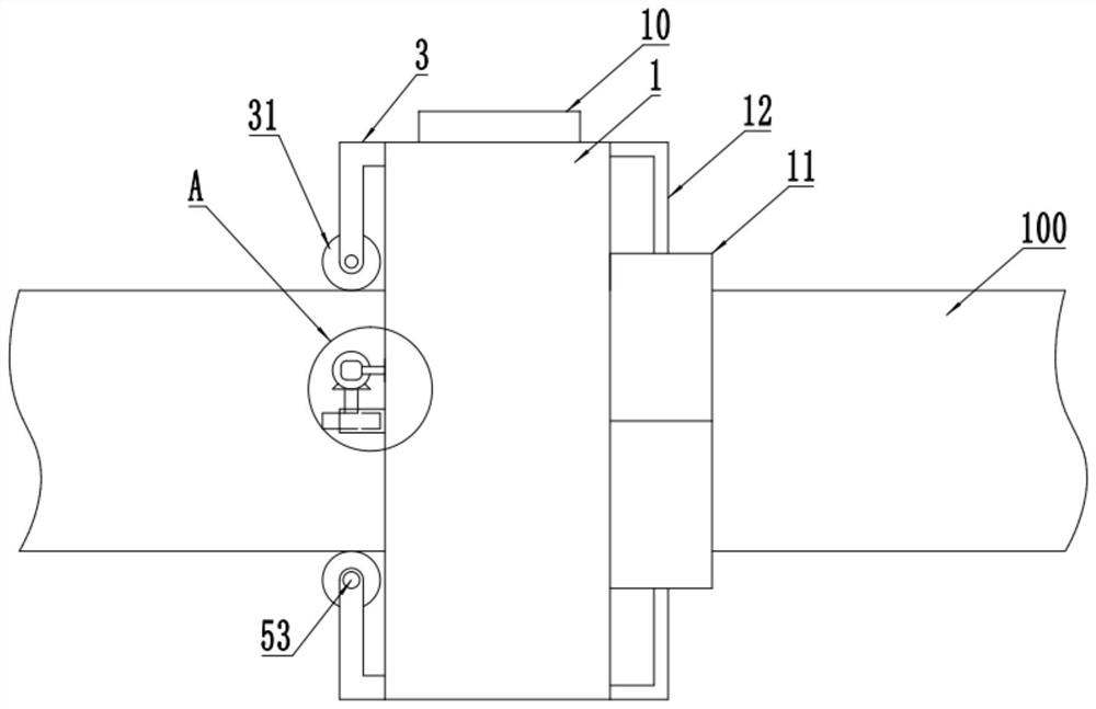
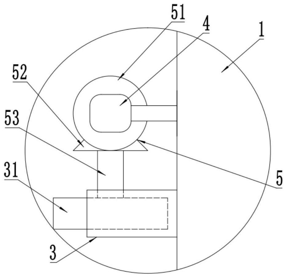
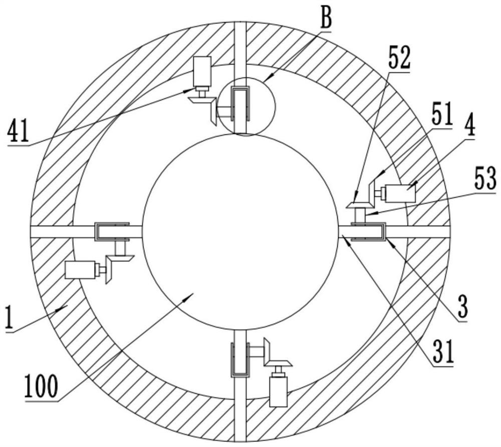
One or more embodiments of the invention provide a cable insulation damage detection device. The device comprises a detection body, used for sleeving on a cable. Grooves are uniformly formed in the inner side wall of the detection body along the circumferential direction at intervals. A first metal contact piece is arranged between every two adjacent grooves. One end of the elastic rod is insertedinto the groove, and a spring is fixedly connected to the connecting rod, the other end abuts against the outer side wall of the cable, to compress the spring. Therefore, the second metal contact piece contacts and is communicated with the first metal contact piece. The loop is conducted, and the motor is triggered to drive the walking wheels to rotate, to drive the detection body to walk. The other side, far away from the wheel carrier, of the detection body clings to the outer side wall of the cable through a pressing plate, opposite friction force is provided through the walking wheel andthe pressing plate, so that the elastic rod is pushed by the spring to slidably extend into the insulation damage, the second metal contact piece is moved away from the first metal contact piece to disconnect the loop so as to stop detection, and automatic and comprehensive insulation damage detection is realized.

Description

technical field [0001] One or more embodiments of this specification relate to the field of cable detection equipment, and in particular to a cable insulation damage detection device. Background technique [0002] A cable usually includes a cable core and an insulating sheath, and the insulation of the cable is extremely important for the safe use of the cable. On the one hand, in the production process of the cable, the insulation layer of the cable needs to be strictly tested to ensure compliance with the use standards. On the other hand, since the long-term use of the cable will affect the insulation effect of the cable to cause insulation damage, which may easily cause serious leakage or electric shock accidents, it is necessary to regularly detect the cable insulation damage, and the existing cable insulation detection device , most of the cables are detected by manually moving the detection probe. For longer cable detection, it is obviously time-consuming and laborious...

Claims


Application Information

Patent Timeline
Patent Type & Authority Applications(China)
IPC IPC(8): G01R31/12
CPCG01R31/1272
Inventor 何仙章健
Owner 匠桥智谷科技(涡阳)有限公司
Why Eureka
Try Eureka