

Fire indication escape equipment for underground engineering
An underground engineering and indication technology, which is applied in the direction of display devices, cleaning methods and appliances, and cleaning methods using gas flow, etc., can solve problems such as damage to indicator lights, unclear guidance for underground workers, and cumbersome operations, etc., to achieve convenient installation, Improved sensitivity and easy operation
- Summary
- Abstract
- Description
- Claims
- Application Information
AI Technical Summary
Problems solved by technology
Method used
Image

Examples
Embodiment 1
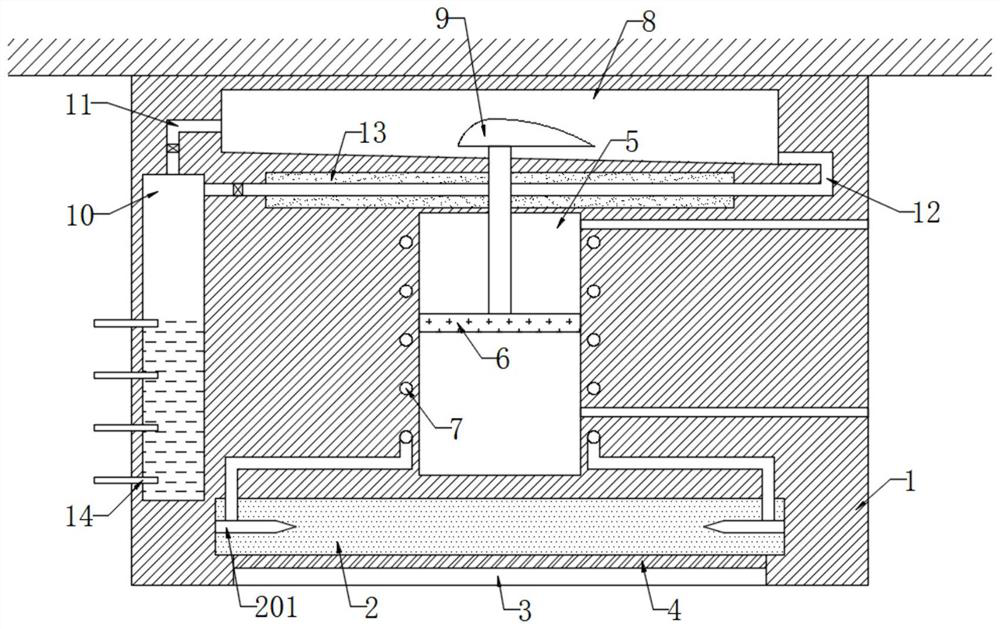
[0022] refer to figure 1 , a fire indication and escape equipment for underground engineering, comprising an indication box 1, a luminous cavity 2 is provided at the lower end of the indicator box 1, and the luminous cavity 2 is filled with neon gas, further, when a low-voltage discharge is performed in the neon gas, the neon gas will Produces orange-red light, the bottom of the light-emitting chamber 2 is provided with a frame opening 3, the inner wall of the frame opening 3 is fixedly connected with a transparent plate 4, and the indicator box 1 is provided with a slide chamber 5, which is sealed and slidably connected with a magnetic slide Plug 6, it should be noted that the inner wall of the slider cavity 5 is symmetrically provided with through holes communicating with the outside world to balance the air pressure change generated when the magnetic slider 6 slides in the slider cavity 5, and the inner wall of the slider cavity 5 is embedded with There is a helical coil 7,...
Embodiment 2
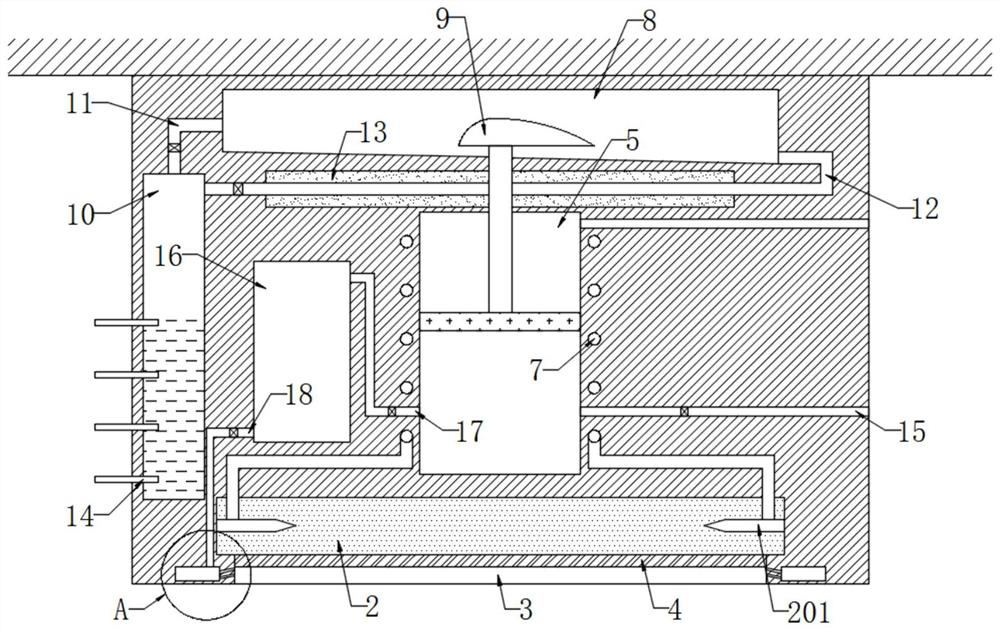
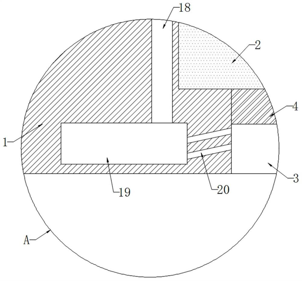
[0026] refer to Figure 2-3 , and the difference from the first embodiment is that a one-way suction pipe 15 is connected under the inner wall of the slide chamber 5, and an air storage chamber 16 is opened in the indicator box 1, and the inner wall of the slide chamber 5 connects with the air storage chamber 16 through a one-way air guide pipe 17 The inner wall is connected. It should be noted that the one-way suction pipe 15 only allows gas to enter the slide chamber 5 from the outside, and the one-way air guide pipe 17 only allows gas to enter the air storage chamber 16 from the slide chamber 5. The side wall of the frame opening 3 An annular chamber 19 is provided, and the inner wall of the gas storage chamber 16 is connected to the annular chamber 19 through a connecting pipe 18. A pressure relief valve is installed in the connecting pipe 18. The inner wall of the annular chamber 19 is provided with a plurality of air injection holes 20 inclined toward the transparent plat...
PUM
| Property | Measurement | Unit |
|---|---|---|
| Boiling point | aaaaa | aaaaa |
Abstract
Description
Claims
Application Information