Power-on guide rail and rail socket

A technology of energized guide rails and guide rails, applied in the direction of circuits, electrical components, coupling devices, etc., can solve problems such as large friction, wear, and guide rail thickness, and achieve the effects of reduced friction area, small volume, and reduced wear

Pending Publication Date: 2020-10-16
BULL GRP CO LTD
View PDF0 Cites 2 Cited by
  • Summary
  • Abstract
  • Description
  • Claims
  • Application Information

AI Technical Summary

Problems solved by technology

[0005] Since both the L pole conductor and the N pole conductor adopt a larger socket structure, not only the guide rail is

Method used


Image

  • Power-on guide rail and rail socket
  • Power-on guide rail and rail socket
  • Power-on guide rail and rail socket

Examples


Embodiment Construction

[0071] In order to make the technical solutions and advantages of the present disclosure clearer, the embodiments of the present disclosure will be further described in detail below in conjunction with the accompanying drawings.

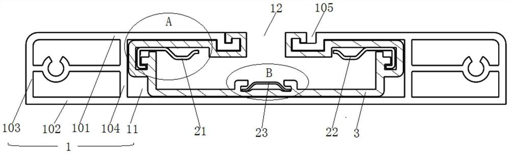
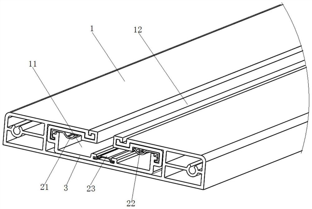
[0072] The track socket is a mobile socket, including: an electrical connector and an electrified guide rail, wherein the electrified guide rail is used for power supply, the electrical connector is used for taking power, the electrical connector slides along the electrified guide rail, and can be used at any position on the electrified guide rail to get electricity. When the external electrical device and the electrical connector are electrically connected, for example, by plugging in, a conductive path is formed by the energized guide rail, the electrical connector, and the external electrical device, so as to realize the power supply of the energized guide rail to the external electrical device. Since the electrical connector in the track socket i...


PUM


Abstract

The invention relates to a power-on guide rail and a rail socket, which belong to the field of electrical devices. The power-on guide rail comprises a guide rail body, a first conducting strip, a second conducting strip and a third conducting strip, wherein a containing cavity extending in the length direction is formed in the guide rail body, an opening extending in the length direction is formedin the top of the guide rail body, and the opening communicates with the containing cavity. The first conducting strip and the second conducting strip are located on the inner sides of the top wallsof the containing cavities on the two sides of the opening respectively and extend in the length direction of the guide rail body, and the bottoms of the first conducting strip and the second conducting strip are used for electric contact. The third conducting strip is located on the inner side of the bottom wall of the containing cavity and extends in the length direction of the guide rail body,and the top is used for electric contact. One of the first conducting strip and the second conducting strip is an L-pole conducting strip, the other one is an N-pole conducting strip, and the third conducting strip is an E-pole conducting strip. The thickness of the power-on guide rail is small, and the electric contact area between the first conducting strip and the electric connector and the electric contact area between the second conducting strip and the electric connector are small, thereby facilitating friction reduction and abrasion reduction.

Description

technical field [0001] The present disclosure relates to the field of electrical devices, in particular to an electric guide rail and a rail socket. Background technique [0002] The track socket is a kind of socket assembled at different positions of the energized guide rail, so that the user can take electricity at any position where the guide rail is arranged. [0003] In the related art, the track socket includes: an electric guide rail and an electrical connector, wherein, the inside of the electric guide rail has an accommodation cavity extending along the length direction, wherein the opposite side walls of the accommodation cavity have L-pole conductors with a socket structure respectively and N-pole conductors, the bottom wall of the accommodating cavity has an E-pole conductor; the bottom of the electrical connector has elastic contact pins corresponding to the above-mentioned conductors. After the electrical connector is assembled into the accommodating cavity of...

Claims


Application Information

Patent Timeline
IPC IPC(8): H01R25/14
CPCH01R25/14H01R25/145
Inventor 郑立和王会玖余超
Owner BULL GRP CO LTD
Why Eureka
Try Eureka