Rotor, asynchronous machine and use of a pressure disc

An asynchronous motor and rotor technology, which is applied to asynchronous induction motors, electromechanical devices, electrical components, etc., can solve the problems that the tie rod cannot be set and is disadvantageous, and achieve the effects of saving manufacturing costs, simplifying costs, and preventing thermal stress.

Active Publication Date: 2020-10-16
THYSSENKRUPP AG
View PDF19 Cites 2 Cited by
  • Summary
  • Abstract
  • Description
  • Claims
  • Application Information

AI Technical Summary

Problems solved by technology

Therefore, tie rods cannot be placed in the outer area
Furthermore, the mounting of the tie rods in the radially inner region of the rotor disc is mechanically and magnetically disadvantageous

Method used


Image

  • Rotor, asynchronous machine and use of a pressure disc
  • Rotor, asynchronous machine and use of a pressure disc
  • Rotor, asynchronous machine and use of a pressure disc

Examples


Embodiment Construction

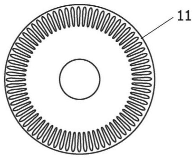
[0072] figure 1 A front view of a lamination stack 11 formed from a plurality of individual laminations is shown. The laminated core 11 has a central through hole. according to figure 1 , the central through hole is configured as a circle. The central through hole can also have other geometric shapes, such as polygons or free-form shapes.

[0073] Furthermore, each lamination of the lamination stack 11 has a plurality of additional through-holes in the outer area region for accommodating the shorting rod 12 . Here, the further through holes are formed by grooves with an elongated shape. The grooves can also have other geometries and / or free shapes. The grooves are formed in the respective laminations radially around the central through hole. Here, the grooves are arranged in a uniform distribution around the central through hole. The grooves can also be arranged differently distributed, in particular distributed in groups, around the central through hole of the respecti...


PUM


Abstract

The present invention relates to a rotor for an asynchronous machine, comprising a rotor shaft (10), rotor elements which are magnetically active in operation and comprise a sheet metal laminated core(11), short-circuit bars (12) and short-circuit rings (13, 14), pressure discs (15, 16), between which at least the sheet metal laminated core (11) is arranged, the pressure discs (15, 16) being axially connected to at least one of the rotor elements, and at least one form-fit element (17) which connects one of the pressure discs (15, 16) and one of the rotor elements, wherein a play or a gap (18) is formed between the sheet metal laminated core (11) and the rotor shaft (10), the pressure discs (15, 16) are connected to the rotor shaft (10) in a torque-transmitting manner and the form-fit element (17) connects one of the pressure discs (15, 16) and one of the rotor elements for transmitting a torque between the rotor shaft (10) and the rotor elements in the circumferential direction of the rotor shaft (10), wherein the torque is introduced by the rotor elements during operation. The invention further relates to an asynchronous machine and to the use of a pressure disc.

Description

technical field [0001] The invention relates to the application of a rotor, an asynchronous motor and a pressure plate. A rotor according to the preamble of claim 1 is known, for example, from EP 2 149 970 B1. Background technique [0002] In the manufacture of the rotor of an electric motor, the magnetically active part of the rotor must be fixed on the rotor shaft. Typically, this part of the rotor consists of stacked laminations. Here, axial permanent magnets integrated into the stacked laminations are provided in a permanent magnet synchronous machine (PSM). In asynchronous machines (ASM) or induction machines, the stacked laminations have integrated, axially arranged shorting bars. It is generally known to use a radial press fit connection in order to transfer torque from the laminations to the rotor shaft of the rotor, eg by shrinking the laminations onto the rotor shaft. [0003] Such a radial press-fit connection is known, for example, from EP 2 149 970 B1 mentio...

Claims


Application Information

Patent Timeline
Patent Type & Authority Applications(China)
IPC IPC(8): H02K1/28H02K17/16
CPCH02K1/28H02K17/165
Inventor 马丁·斯托克托尼·斯坦丹尼尔·保罗
Owner THYSSENKRUPP AG
Why Eureka
Try Eureka