Quick testing equipment for achromatopsia for ophthalmology department
A technology for testing equipment and color blindness, which is applied in the field of rapid testing equipment for color blindness in ophthalmology, and can solve problems such as laboriousness, low randomness, troublesome operation, etc.
- Summary
- Abstract
- Description
- Claims
- Application Information
AI Technical Summary
Problems solved by technology
Method used
Image
Examples
Embodiment 1
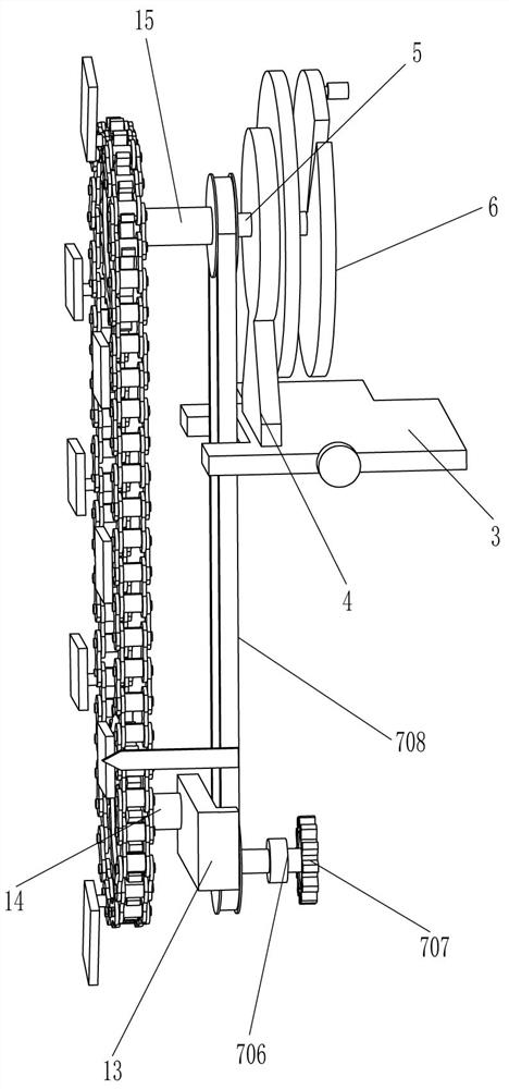
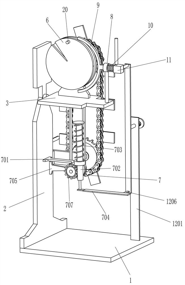
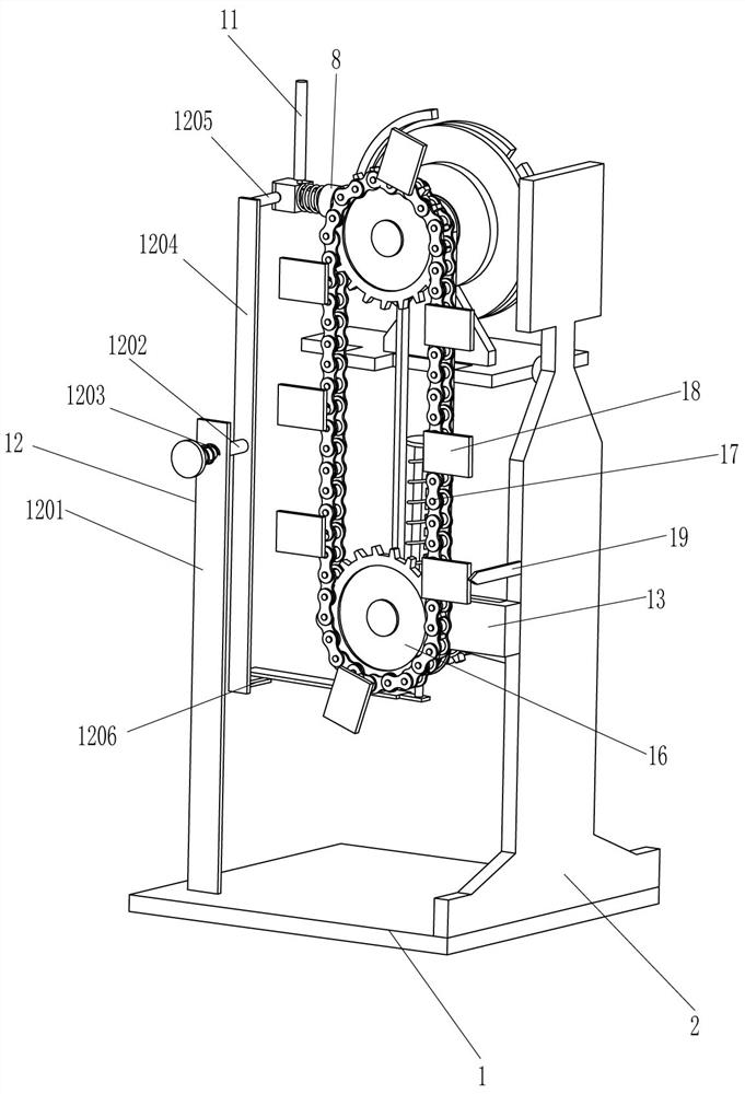
[0021] see Figure 1-Figure 3 , an ophthalmic color blind rapid test equipment, including a base plate 1, a support plate 2, a horizontal plate 3, a vertical plate 4, a rotating shaft 5, a notch plate 6, a driving mechanism 7, a guide sleeve 8, an arc plate 9, and a second spring 10. The movable block 11 and the limit mechanism 12, the support plate 2 is fixedly connected to the left side of the top of the bottom plate 1, the horizontal plate 3 is fixedly connected to the top of the right side of the support plate 2, and the vertical plate is fixed to the left part of the top rear side of the horizontal plate 3 4. The center of the vertical plate 4 is rotatably connected with a rotating shaft 5. The front end of the rotating shaft 5 is fixedly connected with a notch plate 6. A driving mechanism 7 is provided between the rear end of the rotating shaft 5 and the lower part of the right side of the support plate 2. The top of the horizontal plate 3 is on the right side. A guide s...
Embodiment 2
[0028] see figure 1 , figure 2 and image 3 Compared with Embodiment 1, the main difference of this embodiment is that this embodiment also includes an L-shaped plate 13, a first rotating rod 14, a second rotating rod 15, a sprocket 16, a chain 17, a mounting plate 18 and an indication Plate 19, the lower part of the rear side of the support plate 2 is fixedly connected with an L-shaped plate 13, the right part of the outer rear side of the L-shaped plate 13 is rotatably connected with a first rotating rod 14, and the rear end of the rotating shaft 5 is fixedly connected with a second rotating rod 15, The rear end of the second rotating rod 15 and the rear end of the first rotating rod 14 are fixedly connected with a sprocket 16, and a chain 17 is wound between the sprocket wheels 16 on the upper and lower sides, and the rear side of the chain 17 is fixedly connected with a mounting plate evenly spaced circumferentially. 18. An indicator plate 19 is fixedly connected to the...
PUM
 Abstract
Description
Claims
Application Information
 - R&D
- Intellectual Property
- Life Sciences
- Materials
- Tech Scout
- Unparalleled Data Quality
- Higher Quality Content
- 60% Fewer Hallucinations
Browse by: Latest US Patents, China's latest patents, Technical Efficacy Thesaurus, Application Domain, Technology Topic, Popular Technical Reports.
© 2025 PatSnap. All rights reserved.Legal|Privacy policy|Modern Slavery Act Transparency Statement|Sitemap|About US| Contact US: help@patsnap.com


