Silica gel product automatic cutting machine

A cutting machine and product technology, applied in metal processing and other directions, can solve the problems of low cutting efficiency, inaccurate cutting, and inability to realize the automatic unloading function, so as to achieve the effect of improving cutting efficiency and cutting accuracy

Active Publication Date: 2020-10-20
ZHONGSHAN WORLD MEDICAL INSTR
View PDF6 Cites 6 Cited by
  • Summary
  • Abstract
  • Description
  • Claims
  • Application Information

AI Technical Summary

Problems solved by technology

[0005] In order to overcome the shortcomings of inaccurate cutting, low cutting efficiency and the inability to realize the automatic unloading function, the technical problem to be solved is: to provide a silicone product that can quickly cut silicone products, cut accurately, have high cutting efficiency and also Automatic cutting machine for silicone products with automatic feeding

Method used


Image

  • Silica gel product automatic cutting machine
  • Silica gel product automatic cutting machine
  • Silica gel product automatic cutting machine

Examples


Embodiment 1

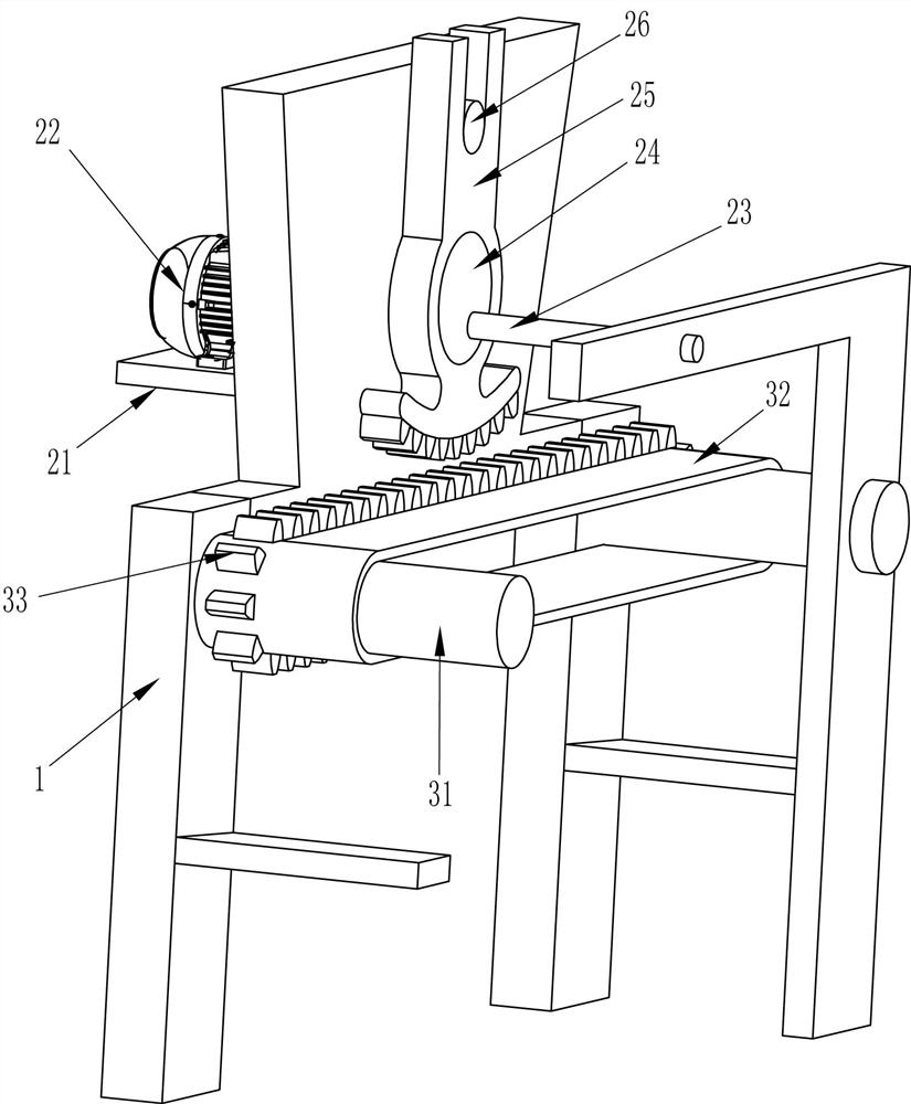
[0050] An automatic cutting machine for silicone products, such as figure 1 As shown, it includes a cutting frame 1, an intermittent drive mechanism 2, an intermittent transmission mechanism 3, a cutting mechanism 4, and a discharge tray 5. The upper part of the cutting frame 1 is equipped with an intermittent driving mechanism 2, and the middle part of the rear side of the cutting frame 1 An intermittent transmission mechanism 3 is installed, and the intermittent transmission mechanism 3 is located below the intermittent driving mechanism 2. A plurality of discharge trays 5 are evenly arranged on the intermittent transmission mechanism 3. The intermittent driving mechanism 2 cooperates with the intermittent transmission mechanism 3, and the cutting frame 1 and the intermittent A cutting mechanism 4 is installed between the driving mechanisms 2 , and the cutting mechanism 4 is located directly above the discharge tray 5 .

[0051] When it is necessary to cut the silicone produ...

Embodiment 2

[0053] On the basis of Example 1, such as Figure 2-4 As shown, the intermittent drive mechanism 2 includes a mounting plate 21, a geared motor 22, a rotating rod 23, a runner 24, a sector gear 25 and a pole 26, and the upper part of the cutting frame 1 rear side is provided with a mounting plate 21, and on the mounting plate 21 Geared motor 22 is installed, and rotating link 23 is connected between cutting frame 1 front and rear both sides top, and rotating bar 23 rear sides are connected with the output shaft of geared motor 22, and the front wall top of cutting frame 1 rear side is provided with support. Rod 26, below the pole 26 is provided with a runner 24, the eccentric part of the runner 24 is connected with the rotating rod 23, a sector gear 25 is set between the pole 26 and the runner 24, the sector gear 25 and the intermittent transmission mechanism 3 Cooperate.

[0054] Intermittent transmission mechanism 3 comprises transmission shaft 31, conveyor belt 32 and toot...

Embodiment 3

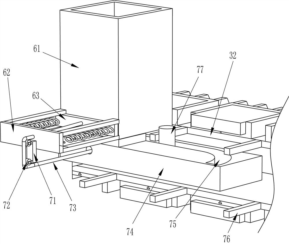
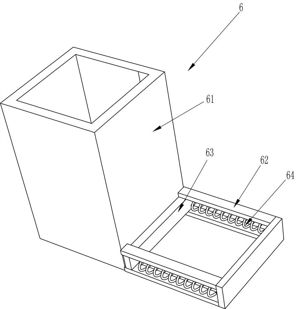
[0060] On the basis of Example 2, such as Figure 5-7 Shown, also include feeding mechanism 6, and feeding mechanism 6 includes placement frame 61, installation frame 62, pusher plate 63 and feed spring 64, and the front side left part of cutting frame 1 is provided with placement frame 61, The lower part of the rear side of the placing frame 61 has an opening, the front side of the placing frame 61 is connected with a mounting frame 62, and the sliding type is connected with a pushing plate 63 in the mounting frame 62, and the pushing plate 63 is positioned at the lower part of the placing frame 61 and cooperates with it. Feeding springs 64 are connected to the left and right parts of the front side of the material plate 63 , and the ends of the feeding springs 64 are connected to the front of the mounting frame 62 .

[0061] Also include feeding auxiliary mechanism 7, feeding auxiliary mechanism 7 includes fixed block 71, guide wheel 72, stay cord 73, fixed plate 74, push ro...


PUM


Abstract

The invention relates to a cutting machine, in particular to a silica gel product automatic cutting machine. The technical problem to be solved is to provide the silica gel product automatic cutting machine which can rapidly cut a silica gel product, can realize precise cutting and high cutting efficiency, and can realize automatic discharging. The silica gel product automatic cutting machine comprises a cutting frame and an intermittent transmission mechanism; an intermittent driving is installed on the upper part of the cutting frame; and the intermittent transmission mechanism is installedon the cutting frame close to one side of the intermittent driving mechanism and is matched with the intermittent driving mechanism. Through matching between a fan-shaped gear and a toothed belt, intermittent motion of a discharging disc is realized; through matching between a circular disc and a lifting slide plate, a cutting tool is driven to move downwardly and conduct rapid cutting of the silica gel product; and through matching between a cylinder and a cylindrical column, the silica gel product is fixed so the cutting tool can realize more precise cutting of the silica gel product.

Description

technical field [0001] The invention relates to a cutting machine, in particular to an automatic cutting machine for silica gel products. Background technique [0002] Silicone products are produced in multiples during injection molding, and multiple products are produced at one time. Therefore, multiple products need to be cut into individual products. The usual cutting method requires manual cutting with a blade , this method cannot meet certain production requirements, and manual cutting is not only inefficient but also has certain potential safety hazards. [0003] Applying for a patent CN209158584U, the publication date is 2019.07.26, which discloses an automatic cutting machine for silicone products, including a frame, several product counties, a county placement plate, a mounting plate, a pair of jig positioning clips, and a cutting mechanism and the operation button, the cutting mechanism includes a cutting knife module, a pair of guide columns, a cutting cylinder a...

Claims


Application Information

Patent Timeline
Patent Type & Authority Applications(China)
IPC IPC(8): B26D1/08B26D5/16B26D5/22B26D7/02B26D7/06
CPCB26D1/08B26D5/16B26D5/22B26D7/02B26D7/0625B26D7/0608
Inventor 钟永锋
Owner ZHONGSHAN WORLD MEDICAL INSTR
Why Eureka
Try Eureka