Forestry log auxiliary cutting device

A technology for cutting devices and logs, which is applied in the direction of clamping devices, feeding devices, circular saws, etc., and can solve the problems of low efficiency, time-consuming and labor-intensive cutting process, and inability to automatically feed materials.

Active Publication Date: 2020-10-20
湖南森海碳汇开发有限责任公司
View PDF6 Cites 12 Cited by
  • Summary
  • Abstract
  • Description
  • Claims
  • Application Information

AI Technical Summary

Problems solved by technology

[0005] In order to overcome the disadvantages of the existing forestry wood cutting device, which has a relatively fixed structure and cannot automatically feed materials, manual continuous feeding is time-consuming and labor-intensive, and results in low efficiency in the cutting process, the technical problem is to provide an automatic feeding device that is convenient for cutting. Auxiliary cutting device for forestry round logs

Method used


Image

  • Forestry log auxiliary cutting device
  • Forestry log auxiliary cutting device
  • Forestry log auxiliary cutting device

Examples


Embodiment 1

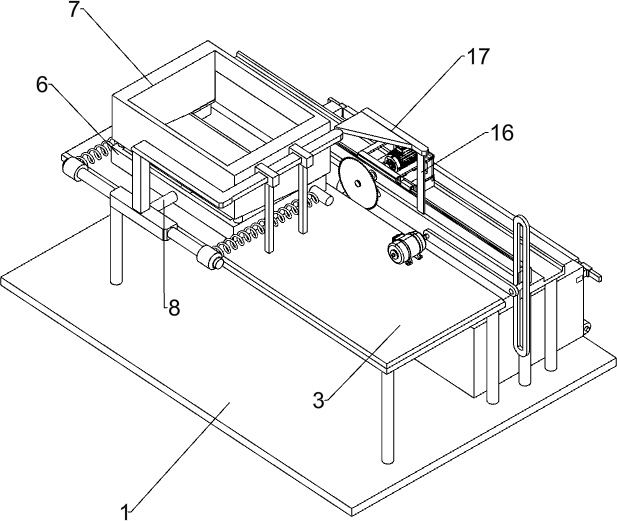
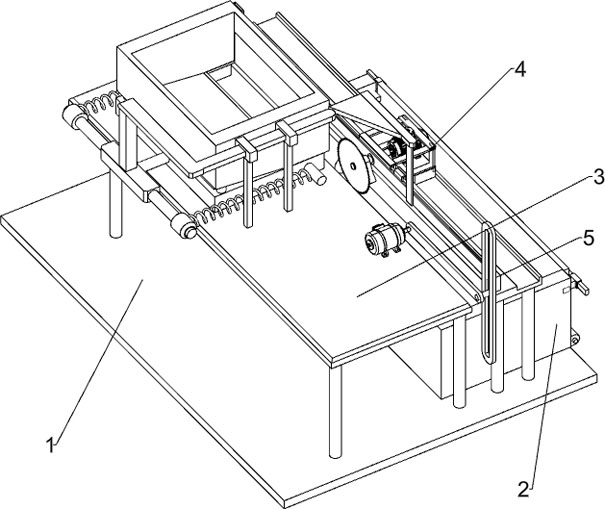
[0024] Such as Figure 1-3 As shown, a forestry log auxiliary cutting device includes a base 1, a collection box 2, a workbench 3, a cutting device 4 and a moving device 5, the rear side of the top of the base 1 is provided with a collection box 2, and the middle part of the top of the base 1 is provided with a The workbench 3 is provided with a cutting device 4 on the rear side of the top of the base 1. The cutting device 4 is located directly above the collection box 2. The workbench 3 is provided with a moving device 5 that drives the cutting device 4 to reciprocate.

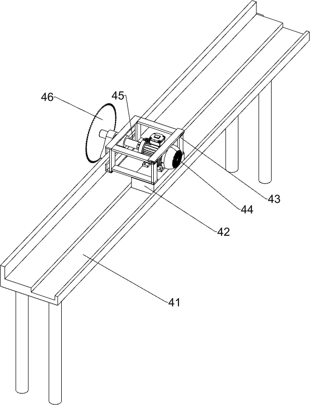
[0025] Cutting device 4 comprises slide rail 41, slide block 42, mounting frame 43, servomotor 44, rotating shaft 45 and circular saw 46, and base 1 top rear side is provided with slide rail 41, and slide rail 41 is provided with sliding type. Block 42, slide block 42 is provided with mounting frame 43, is provided with servomotor 44 in the mounting frame 43, and the output shaft of servomotor 44 is connected...

Embodiment 2

[0029] On the basis of Example 1, such as Figure 4-6 As shown, it also includes N-shaped frame 6, blanking frame 7, sliding rod 8, push plate 9, baffle plate 10, fixed frame 11, fixed block 12, elastic member 13, guide sleeve 14, special-shaped connecting rod 15, connecting Rod 16 and wedge block 17, N-shaped frame 6 is arranged on the left side of the top of the workbench 3, the top of the N-shaped frame 6 is provided with a blanking frame 7, the middle part of the N-shaped frame 6 is slidingly provided with a sliding rod 8, and the rear end of the sliding rod 8 A push plate 9 is provided, the top of the push plate 9 is provided with a baffle 10, the baffle 10 cooperates with the discharge port of the blanking frame 7, the front end of the sliding rod 8 is provided with a fixed frame 11, and the rear part of the left and right side walls of the N-shaped frame 6 is symmetrical A fixed block 12 is provided, and an elastic member 13 is arranged between the fixed block 12 and th...


PUM


Abstract

The invention relates to a cutting device, in particular to a forestry log auxiliary cutting device. The forestry log auxiliary cutting device achieves the technical purposes of automatic dischargingand convenient cutting. According to the technical scheme, the forestry log auxiliary cutting device comprises a base the top side edge of which is provided with a collecting box; a workbench which isarranged in the middle of the top of the base; a cutting device which is arranged at the position, close to the workbench, of the top of the base, and is located over the collecting box; and a movingdevice which is used for driving the cutting device to reciprocate and is arranged on the workbench. The cutting device achieves the effects of automatic discharging and convenient cutting.

Description

technical field [0001] The invention relates to a cutting device, in particular to an auxiliary cutting device for forestry round logs. Background technique [0002] Forestry refers to the production sector that protects the ecological environment and maintains ecological balance, cultivates and protects forests to obtain timber and other forest products, and utilizes the natural characteristics of forest trees to play a protective role. It is one of the important components of the national economy. In the human and biosphere, forestry is engaged in the cultivation, protection, and utilization of forest resources through advanced science and technology and management methods, to make full use of the multiple benefits of forests, and to manage forest resources sustainably. [0003] In the process of forestry production, round logs need to be cut and segmented. The segmented wood is convenient for the next half-cutting process. The existing forestry wood cutting device has a r...

Claims


Application Information

Patent Timeline
Patent Type & Authority Applications(China)
IPC IPC(8): B27B5/065B27B5/18B27B29/02B27B31/00B27B31/08B27B5/29
CPCB27B5/065B27B5/181B27B5/187B27B29/02B27B31/00B27B31/08B27B5/29Y02A40/28
Inventor 胡细平
Owner 湖南森海碳汇开发有限责任公司
Why Eureka
Try Eureka