
Rotary fan blade and electric appliance

A technology of fan blades and electrical appliances, which is applied in the direction of machines/engines, components of pumping devices for elastic fluids, non-variable pumps, etc., and can solve problems such as large noise of rotating fan blades and adverse effects on users

Inactive Publication Date: 2020-10-20
GREE ELECTRIC APPLIANCES INC
View PDF6 Cites 0 Cited by
  • Summary
  • Abstract
  • Description
  • Claims
  • Application Information

AI Technical Summary

Problems solved by technology

[0002] Existing electrical appliances such as rotating fans are equipped with rotating fan blades, and most of the blades in the existing rotating fan blades are arranged to be evenly distributed along the circumferential direction. adversely affect users

Method used


Image

  • Rotary fan blade and electric appliance
  • Rotary fan blade and electric appliance
  • Rotary fan blade and electric appliance

Examples


Embodiment 1

[0018] The electrical appliance in this embodiment can be, for example, an air conditioner, and the electrical appliance includes an axial fan, and the axial fan includes the rotating blade of this embodiment.

[0019] Optionally, the electrical appliance of the present invention may also be other electrical appliances such as a rotating fan.

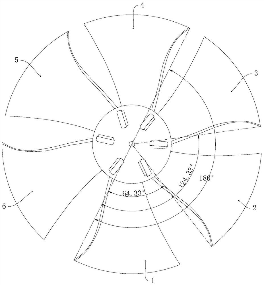
[0020] Please refer to figure 1 , the rotating fan blade in this embodiment has six blades, the six blades are respectively the first blade 1, the second blade 2, the third blade 3, the fourth blade 4, the fifth blade 5 and the sixth blade 6, the first The blade 1, the second blade 2, the third blade 3, the fourth blade 4, the fifth blade 5 and the sixth blade 6 are distributed in the counterclockwise direction, the first blade 1 is the first blade, and the second blade 2 is the first blade. 2 blades, the third blade 3 is the 3rd blade, the fourth blade 4 is the 4th blade, the fifth blade 5 is the 5th blade, the sixth blade is the 6th ...

Embodiment 2

[0034] In the rotating fan blade of this embodiment, the amplitude modulation coefficient ξ is 13, and each θ' i ,δ i with The values ​​are shown in the table below:

[0035]

[0036]

[0037] As can be seen from the above table, the present embodiment

[0038] In this embodiment

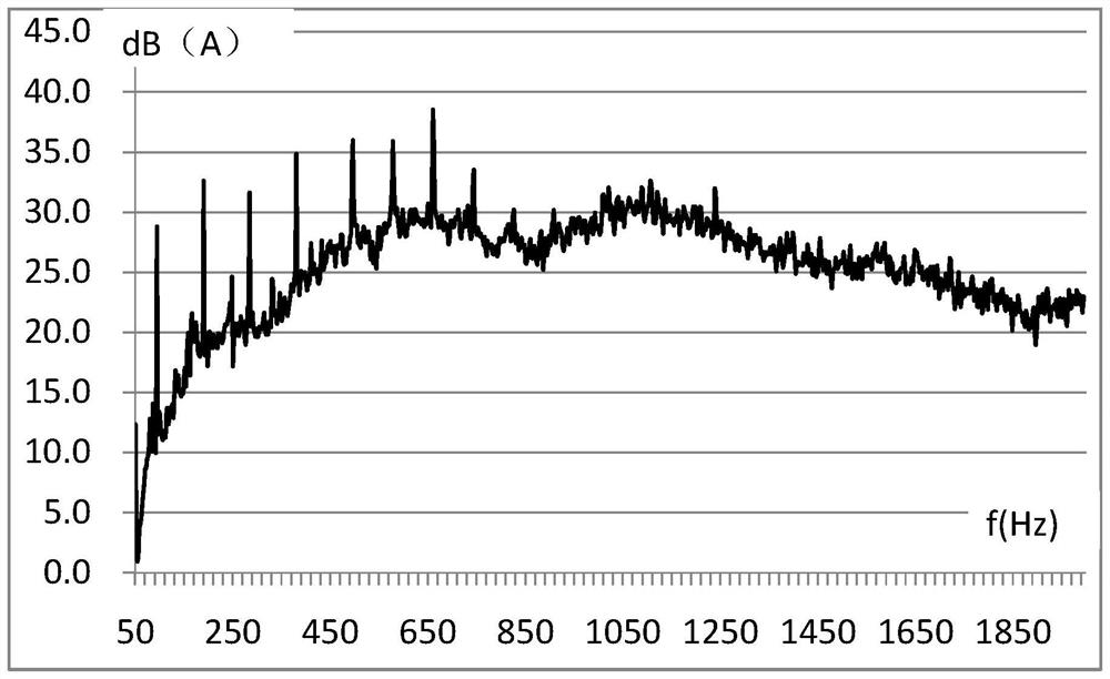
[0039] In order to verify the noise reduction effect of the rotating fan blade of this embodiment, the rotating noise detection is carried out on the rotating fan blade of this embodiment, and the rotating speed is 950 rpm. Figure 4 as shown, Figure 4 In , the abscissa is the noise frequency, and the ordinate is the noise decibel value.

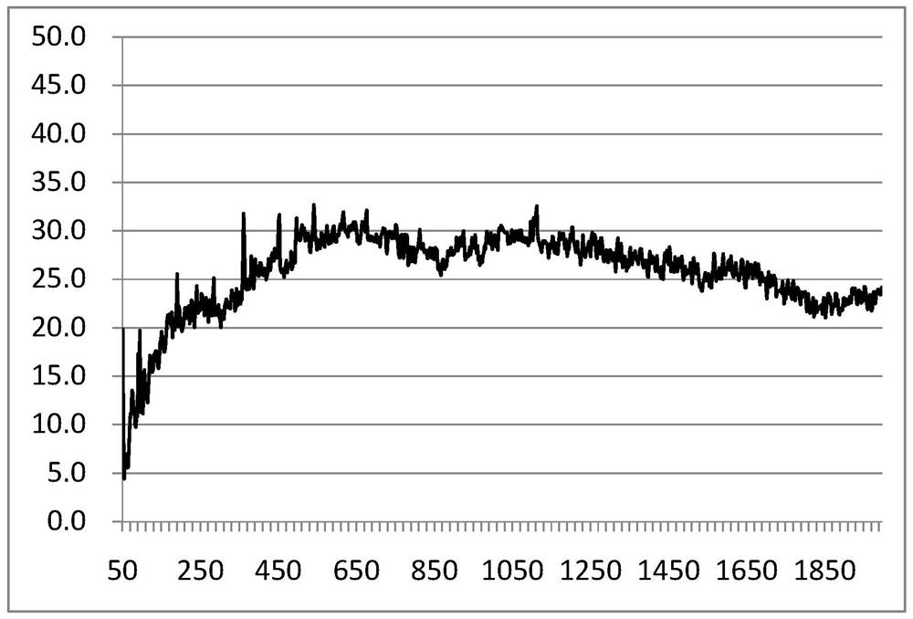
[0040] Depend on Figure 4 and image 3 It can be seen from the comparison that in the noise spectrum within 2000 Hz, the highest peak value of the rotating fan blades with six blades equally spaced is 38dB, and the highest peak value of high-decibel noise in the noise spectrum generated by the rotating fan blades in this embodiment is 33dB....


PUM


Abstract

The invention relates to the field of blades, and provides a rotary fan blade and an electric appliance. The rotary fan blade comprises at least three blades which are distributed in the circumferential direction, wherein a distribution angle of each blade meets the following relation that theta is equal to 360i / n (i is equal to 1,..., n-1), theta' is equal to theta plus xi sin theta (i is equal to 1,..., n-1, xi is not equal to 0) (see the detailed description in the specification), n represents the total number of the blades, theta' represents the angle from the first blade tothe (i plus 1)th blade along a first hour hand direction, xi is an amplitude modulation coefficient, and all relational expressions are established by adjusting the value of xi. Compared with the scheme that the fan blades are evenly distributed, noise generated by the rotary fan blade is lower, because of the equation described in specification, a rotating eccentricity ratio of the rotary fan blade is small and the dynamic balance performance is good, and large noise cannot be generated by parts connected with the rotary fan blade in the rotating process of the rotary fan blade, so that theoverall noise of the electric appliance applying the rotary fan blade is low.

Description

technical field [0001] The invention relates to the field of rotating blades, and provides a rotating blade and an electrical appliance. Background technique [0002] Existing electrical appliances such as rotating fans are equipped with rotating fan blades, and most of the blades in the existing rotating fan blades are arranged to be evenly distributed along the circumferential direction. adversely affect users. Contents of the invention [0003] One of the objects of the present invention is to provide a rotating fan blade which operates with relatively low noise and does not cause relatively loud noises to its connected components. [0004] In order to achieve the above object, the rotary fan blade provided by the present invention includes at least three blades, and each blade is distributed along the circumferential direction; the distribution angle of each blade satisfies the following relationship: θ i =360°×i / n(i=1,...,n-1); θ' i = θ i +ξsinθ i (i=1,...,n-1; ξ...

Claims


Application Information

Patent Timeline
IPC IPC(8): F04D29/32F04D29/66
CPCF04D29/328F04D29/666
Inventor 李彬杨伟奇李小辉肖彪
Owner GREE ELECTRIC APPLIANCES INC
Learn More