Calibration device for laser displacement sensor

A calibration device and laser displacement technology, applied in the field of laser calibration, can solve problems such as inability to define laser displacement sensors and difficult adjustments

Pending Publication Date: 2020-10-20
苏州威达智科技股份有限公司
View PDF0 Cites 2 Cited by
  • Summary
  • Abstract
  • Description
  • Claims
  • Application Information

AI Technical Summary

Problems solved by technology

[0002] Laser displacement sensors are often used to measure the structural stability of products (such as computer touch panels, etc.) under simulated working conditions, but the measurement accuracy requires high requirements, up to 0.001mm, so parameter setting and calibration of laser displacement sensors are required , in order to be able to obtain accurate data, but when calibrating the laser displacement sensor, generally only rely on experience to adjust the parameters of the laser displacement sensor, it is impossible to define whether the laser displacement sensor is adjusted to a relatively stable use state, and adjust also more difficult

Method used


Image

  • Calibration device for laser displacement sensor
  • Calibration device for laser displacement sensor
  • Calibration device for laser displacement sensor

Examples


Embodiment Construction

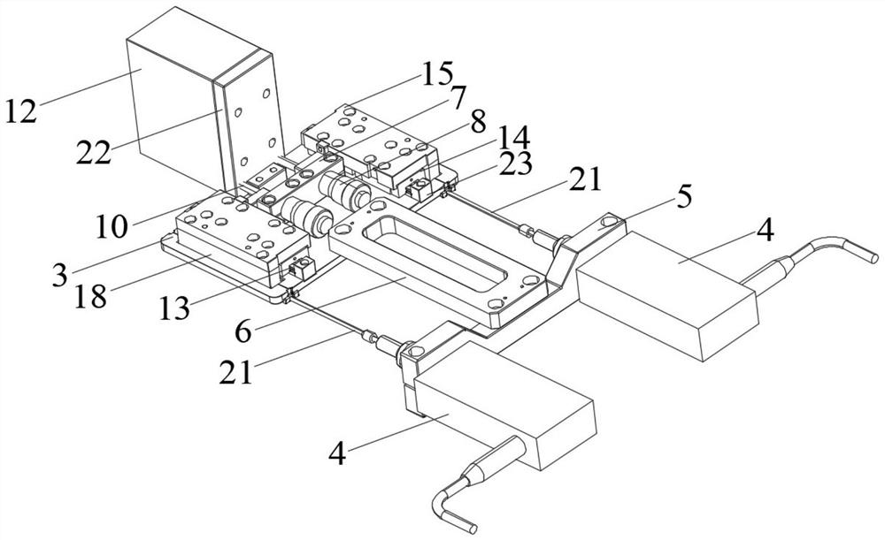
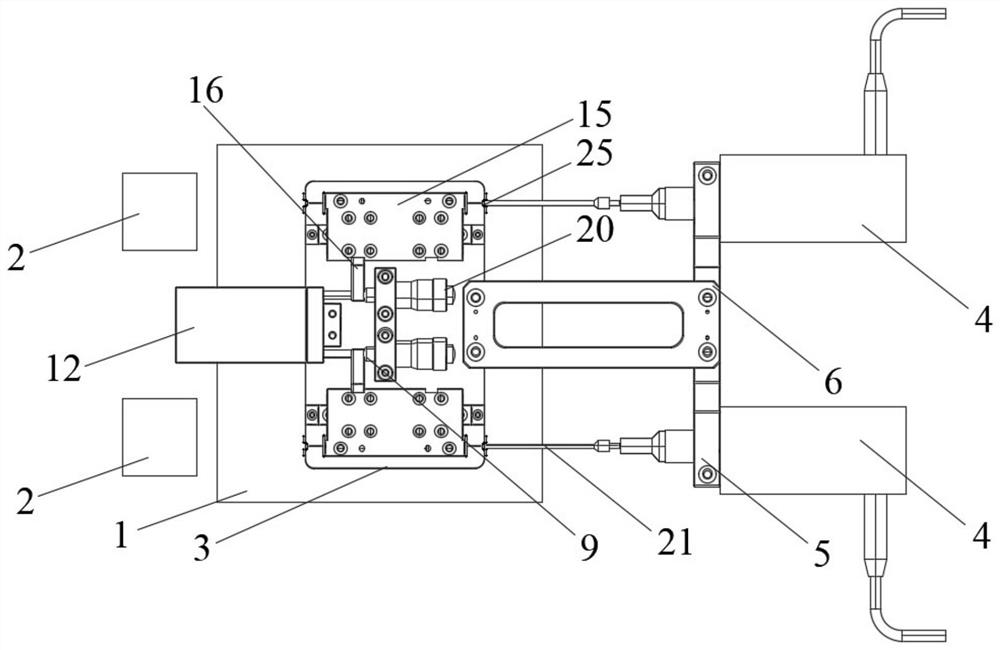
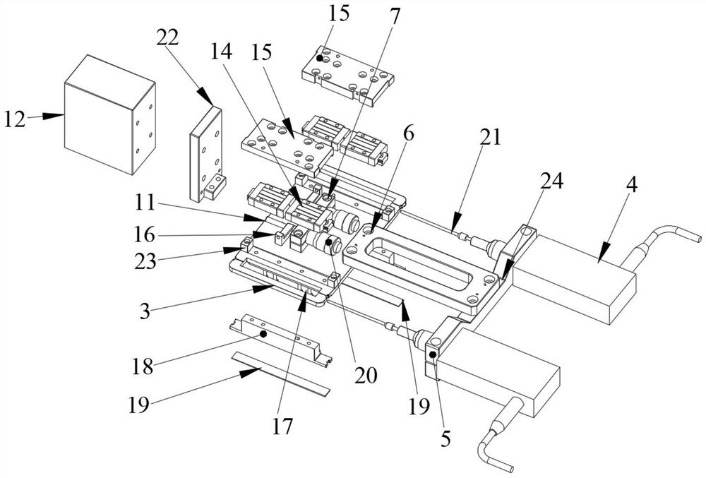
[0018] Such as Figure 1 to Figure 5 As shown, the present invention is used for the calibration device of the laser displacement sensor, after being placed on the special jig 1 for detecting the position of the product to be tested, and the calibration side of the calibration device (being the side close to the counterweight 12) and The laser displacement sensor 2 is relatively set, and the special fixture 1 can be set according to the needs of the manufacturer to detect the product under test. The calibration device in this patent only needs to be placed on the special fixture 1 for detecting the product under test. , no specific requirements are required for the special fixture 1; the calibration device includes a laser calibration plate 3 and a multimeter 4, that is, the laser calibration plate 3 is placed on the special fixture 1 for detecting the position of the product to be tested, and the multimeter 4 is mounted on a fixed On the plate 5, the laser calibration plate 3...


PUM


Abstract

The invention provides a calibration device for a laser displacement sensor. Laser parameters can be conveniently calibrated; the device comprises a laser calibration plate and a dial indicator, the dial indicator is arranged on a fixed plate; the laser calibration plate and the fixed plate are connected through a mounting connecting block; a micrometer head mounting plate is mounted on the lasercalibration plate; a micrometer is assembled on the micrometer head mounting plate; a sleeve and a screw rod on the micrometer penetrate through the micrometer head mounting plate; the screw rod is connected with a balancing weight through a compression spring; a sliding assembly is arranged on the laser calibration plate; the sliding assembly comprises a sliding rail, a sliding plate is arrangedon the sliding rail through a sliding block; the sliding plate is connected with the screw rod through a follow-up block; a through groove is formed in the laser calibration plate below the sliding plate; the upper portion of an inverted-T-shaped side sliding block penetrates through the through groove and then is connected with the bottom face of the sliding plate, the length of the through groove is larger than that of the upper portion of the side sliding block and smaller than that of the lower portion of the side sliding block, optical glass is installed on the bottom face of the lower portion of the side sliding block, and a probe on the dial indicator penetrates through the fixed plate and then makes contact with the optical glass.

Description

technical field [0001] The invention relates to the technical field of laser calibration, in particular to a calibration device for a laser displacement sensor. Background technique [0002] Laser displacement sensors are often used to measure the structural stability of products (such as computer touch panels, etc.) under simulated working conditions, but the measurement accuracy requires high requirements, up to 0.001mm, so parameter setting and calibration of laser displacement sensors are required , in order to be able to obtain accurate data, but when calibrating the laser displacement sensor, generally only rely on experience to adjust the parameters of the laser displacement sensor, it is impossible to define whether the laser displacement sensor is adjusted to a relatively stable use state, and adjust It is also more difficult. Contents of the invention [0003] In order to solve the above-mentioned problems in the prior art, the present invention provides a calib...

Claims


Application Information

Patent Timeline
Patent Type & Authority Applications(China)
IPC IPC(8): G01B11/02
CPCG01B11/02G01B21/042
Inventor 夏坤王跃跃
Owner 苏州威达智科技股份有限公司
Why Eureka
Try Eureka