
A Fault Location Method for Fully Parallel AT Traction Network
A technology of fault distance measurement and traction network, which is applied to fault location, fault detection according to conductor type, and electrical measurement, etc., which can solve problems such as poor adaptability and complex implementation
Patent Information
- Authority / Receiving Office
- CN · China
- Patent Type
- Patents(China)
- Current Assignee / Owner
- Publication Date
- 2021-04-13
Smart Images
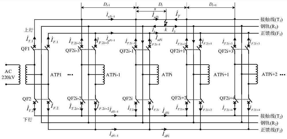
Figure 1 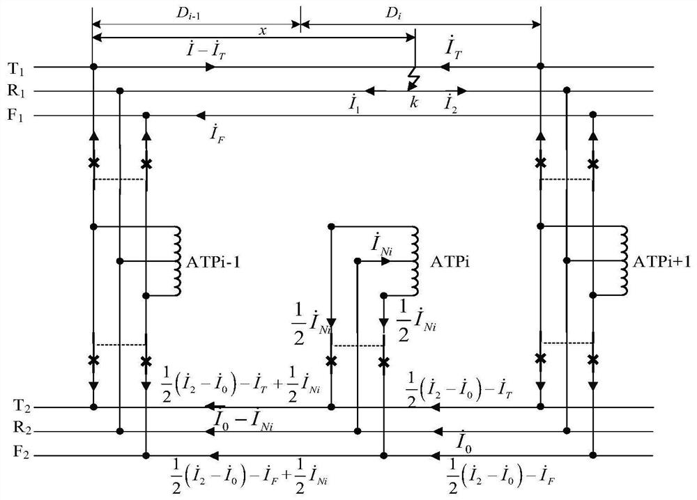
Figure 2 
Figure 3
Abstract
Description
technical field
[0001] The invention relates to an electrified railway traction network technology, in particular to a fault location method for a fully parallel AT traction network. Background technique
[0002] The traction network of electrified railway has the characteristics of complex structure and high failure rate. Accurate and reliable fault location is very important for quickly finding fault points, repairing fault lines in time, shortening power outage time and ensuring transportation order.
[0003] The power supply operation mode of the fully parallel AT traction network is determined by the opening and closing states of its various switches. In normal power supply operation mode, all traction network switches are closed. However, due to the different power supply requirements of users, some equipment failures or the withdrawal of maintenance and other reasons, some circuit breakers of the traction network will be disconnected, and the traction network is in a...
Examples
Embodiment Construction
[0071] The specific embodiments of the present invention will be further described below with reference to the accompanying drawings.
[0072] In general, the fully parallel AT traction network has 2-3 AT segments. But in the case of cross-regional power supply, etc., the traction network AT segment can reach 4-6. In order to express the generality of the method of the present invention, figure 1 Indicates a fully parallel AT traction network. In the figure, ATP1 represents the traction substation, ATPi (i=2...n, where n≥3) represents the AT station or sub-station, T, R, F represent the contact line, rail, and positive feeder respectively, D i (i=1...n-1) represents the length of each power supply section, QF 2i-1 (i=1...n), QF 2i (i=1...n) represent the bipolar feeder circuit breakers of the upper and lower pavilions, respectively, Respectively represent the circuit breaker QF 2i-1 , QF 2i The T line current flowing through; Respectively represent the circuit breake...