Scenic spot geographic information display equipment

A technology of geographic information and display equipment, applied in the field of electronic information, can solve the problems of unclear information expression, insufficient grasp of geographic information status, and vague information display at the top of the mountain.

Inactive Publication Date: 2020-10-20
CHONGQING VOCATIONAL INST OF ENG
View PDF0 Cites 1 Cited by
  • Summary
  • Abstract
  • Description
  • Claims
  • Application Information

AI Technical Summary

Problems solved by technology

[0004] Aiming at the deficiencies in the prior art, the purpose of the present invention is to provide a geographical information display device for scenic spots, so as to solve the sand table electronic data mapping of geographical information in scenic spots. The commonly used desktop plane probes are used for elevation angle interleaved mapping, which will cause mountain tops in the state of mountains in scenic spots. The display of information is blurred, and the focal points of diverging lights are staggered, resulting in unclear and inaccurate information expression, which makes tourists insufficiently aware of the geographic information status of the mountain peak in the scenic spot. , leading to a reduction in the integrity of geographic information display equipment, and the problem of large limitations in the expression of electronic sand table projection in scenic spots

Method used


Image

  • Scenic spot geographic information display equipment
  • Scenic spot geographic information display equipment
  • Scenic spot geographic information display equipment

Examples


Embodiment 1

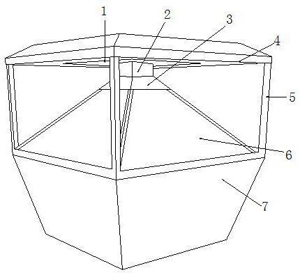
[0033] See Figure 1-Figure 6 , The present invention provides a geographic information display device for scenic spots, the structure of which includes: a ceiling light board 1, a projection plate lifting slot 2, a light beam slot cover 3, a top cover plate 4, a bracket frame slot 5, a glass panel 6, and a power distribution base Box 7, the projection tray hoisting groove 2 is nested on the top of the light beam groove cover 3 and penetrates each other, and the glass panel 6 is inserted and embedded under the bottom of the light beam groove cover 3 and is on the same inclined surface. The panel 6 is installed inside the bracket frame slot 5, the ceiling light board 1 is inserted into the inside of the top cover 4 and is on the same horizontal surface, and the ceiling light board 1 is closely attached to the top of the projection tray lifting groove 2. The power distribution base box 7 is nested under the bottom of the glass panel 6, and the projection tray hoisting slot 2 is p...

Embodiment 2

[0040] See Figure 1-Figure 6 , The present invention provides a geographic information display device for scenic spots. The other aspects are the same as Embodiment 1, except that:

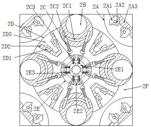
[0041] See figure 2 , The pulling plate wheel 2E is composed of a clamping axle wheel 2E1, an outer ring tray 2E2, and a tie bar 2E3. The clamping axle wheel 2E1 is installed inside the outer ring tray 2E2 and the axis is collinear. The buckle bar 2E3 is buckled together with the clamping shaft wheel 2E1 and is on the same vertical plane. The buckle bar 2E3 is pulled by the clamping shaft wheel 2E1 to form a mapping of the revolving clamping, hoisting and turning cover the three-position scanning sand table processing effect .

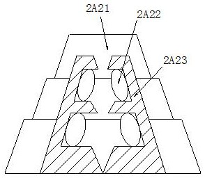
[0042] See Image 6 , The clip axle wheel 2E1 is composed of a flap buckle seat 2E11, an axle wheel body 2E12, a trapezoidal clip plate 2E13, and a thin pole wheel frame 2E14. The flap buckle seat 2E11 and the axle wheel body 2E12 adopt an interference fit , The trapezoidal...


PUM


Abstract

The invention discloses scenic spot geographic information display equipment. The equipment structurally comprises a top lamp plate, a projection disc hoisting groove, a light bundling groove cover, atop cover plate, a support frame groove, a glass panel and a power distribution base box. According to the invention, the cooperation of the top lamp plate and the projection disc hoisting groove isrealized; the top lamp plate is installed at the top of the square shell frame groove, and then the projection lens cone is erected to cooperate with oblique angle settlement mapping to form sand table projection effects of different angles. The top lamp plate is matched with the three-dimensional irradiation of the top to achieve the effect of complementing the picture definition of the bottom end fuzzy mapping; therefore, the mountain parietal area of the whole triangular mountain scenic area is clearly displayed, the coverage area feedback light supplementing operation effect of bottom mountain feet and mountain waists is also driven, the regularity of sand table mapping and the coverage area of the three-dimensional projection lamp bodies at different angles are improved, the precisionof scenic area geographic information display is improved, and it is guaranteed that tourists completely know the scenic area and safely play.

Description

Technical field [0001] The invention is a geographical information display device for scenic spots, belonging to the field of electronic information. Background technique [0002] The road signs and plane environment display boards of the scenic area have certain limitations on the three-dimensional conception of tourists. When the scenic area is equipped with digital electronic sand table three-dimensional projection geographic information display equipment, it will more intuitively improve the understanding of the scenic area. , To ensure the safety of the game, the disadvantages of current technology common to be optimized are: [0003] Sand table electronic data mapping of geographic information in scenic spots often uses desktop planar probes for elevation angle interleaving mapping. This will cause the information display on the top of the mountain in the scenic area to be blurred, and the divergent focus points of the lights will be interlaced, resulting in unclear and inacc...

Claims


Application Information

Patent Timeline
Patent Type & Authority Applications(China)
IPC IPC(8): G09B25/00G09F19/18
CPCG09B25/00G09F19/18
Inventor 李莉
Owner CHONGQING VOCATIONAL INST OF ENG
Why Eureka
Try Eureka