Fire-resistant and high-temperature-resistant control cable and manufacturing method thereof

A technology for controlling cables and high temperature resistance, which is applied in the field of power cables and can solve the problems of cables such as fire resistance, poor high temperature resistance, insufficient tensile and pressure bearing capacity, etc.

Active Publication Date: 2020-10-20
TIANCHANG HUILING ELECTRIC APPLIANCE METER FACTORY
View PDF7 Cites 3 Cited by
  • Summary
  • Abstract
  • Description
  • Claims
  • Application Information

AI Technical Summary

Problems solved by technology

[0003] Existing cables have poor fire resistance, high temperature

Method used


Image

  • Fire-resistant and high-temperature-resistant control cable and manufacturing method thereof
  • Fire-resistant and high-temperature-resistant control cable and manufacturing method thereof
  • Fire-resistant and high-temperature-resistant control cable and manufacturing method thereof

Examples


Embodiment 1

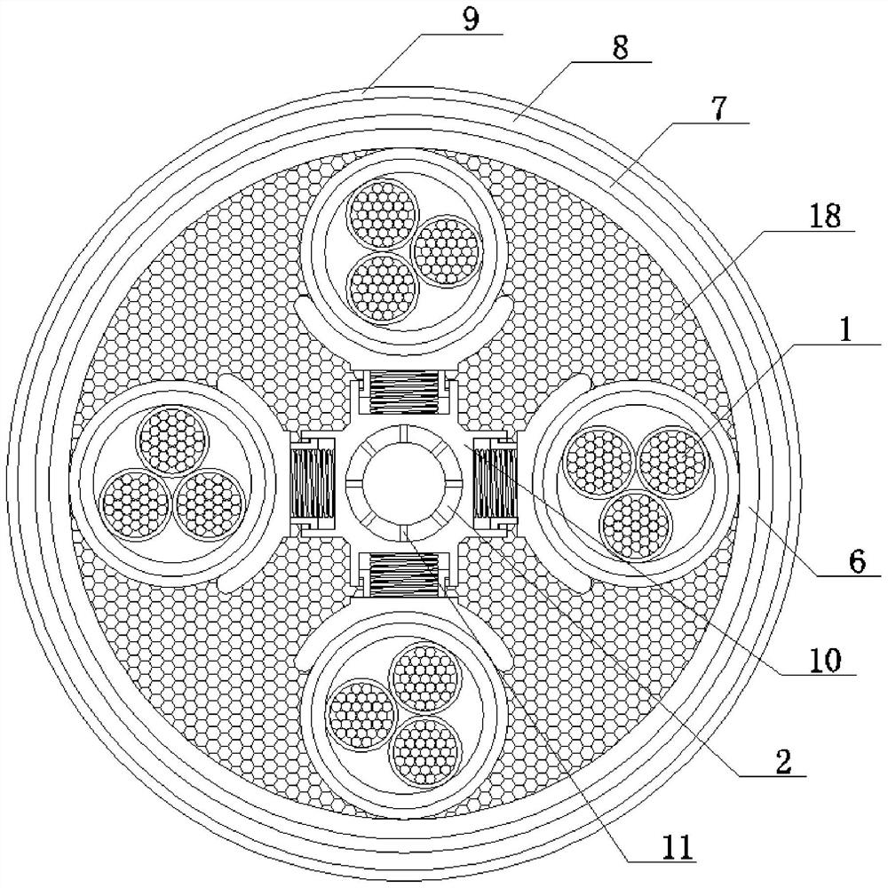
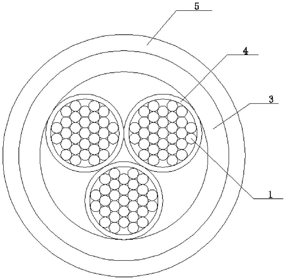
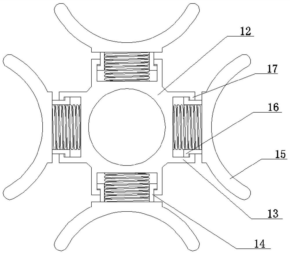
[0037] A fire-resistant and high-temperature-resistant control cable, comprising a plurality of sets of conductors 1, including a heat dissipation strengthening tube 2, the conductor 1 is covered with an insulating layer 4 to form an insulated wire core, and a plurality of insulated wire cores are covered with a braided shielding layer 3, braided The shielding layer 3 is covered with a high temperature resistant loose tube 5 to form the main wire core. Multiple main wire cores are combined and covered with a fireproof heat insulation layer 6, a flame retardant inner sheath 7, a braided armor layer 8 and a flame retardant outer sheath. The sheath 9 and the heat dissipation strengthening tube 2 are located between multiple main wire cores. The heat dissipation strengthening pipe 2 is equidistantly fixedly connected with a plurality of support frames 10 .

[0038] Wherein, the heat dissipation strengthening tube 2 is a polytetrafluoroethylene hose, and the outer peripheral wall of...

Embodiment 2

[0046] A method for preparing a fire-resistant and high-temperature-resistant control cable, comprising the following specific implementation steps:

[0047] Step 1, twisting a plurality of nickel-plated copper wires to form a conductor 1;

[0048] Step 2, extruding a layer of ceramic silicon rubber on the outer periphery of the conductor 1 to form an insulating layer 4, and the insulating layer 4 and the conductor 1 form an insulating core;

[0049] Step 3: Twisting a plurality of insulated wire cores to form an encapsulation body and covering the braided layer of silver-plated copper wire to form the braided shielding layer 3; the braided shielding layer 3 is covered with a high-bulk glass fiber tube, and coated with oxidized Iron-red silica gel forms a high-temperature-resistant loose tube 5; the package body, braided shielding layer 3, and high-temperature loose tube 5 form the main core;

[0050] Step 4: Set a plurality of ventilation holes 11 on the polytetrafluoroethyl...


PUM


Abstract

The invention discloses a fire-resistant and high-temperature-resistant control cable including multiple sets of conductors and including a heat dissipation reinforcing tube, wherein the conductors are coated with insulating layers to form insulating wire cores; the plurality of insulating wire cores are coated with braided shielding layers, the braided shielding layers are coated with high-temperature-resistant loose tubes to form main wire cores, the plurality of main wire cores are combined and are sequentially coated with a fireproof heat-insulating layer, a flame-retardant inner sheath, abraided armor layer and a flame-retardant outer sheath, the heat dissipation reinforcing pipe is located among the plurality of main wire cores, a plurality of support frames are fixedly connected tothe heat dissipation reinforcing pipe at equal intervals, and the fireproof heat-insulating layer is also filled with heat-insulating flame-retardant particles; the heat dissipation reinforcing pipemade of polytetrafluoroethylene is arranged among the main wire cores, the appearance organization is fine, no mechanical impurity exists, the strength is high, the heat dissipation reinforcing tube are located in the center gap of the main wire cores, and the structural stability, the tensile property and the high temperature resistance of the cable are improved. And through a plurality of vent holes in the surface of the heat dissipation reinforcing pipe, a heat dissipation effect can be achieved, and the internal heat resistance of the cable is improved.

Description

technical field [0001] The invention relates to the technical field of power cables, in particular to a fire-resistant and high-temperature-resistant control cable and a manufacturing method thereof. Background technique [0002] Fire-resistant cables refer to cables that can maintain safe operation for a certain period of time under the condition of flame burning. Fire-resistant cables are widely used in high-rise buildings, underground railways, underground streets, large power stations, important industrial and mining enterprises and other places related to fire safety and fire-fighting and lifesaving, such as power supply lines and control lines of emergency facilities such as fire-fighting equipment and emergency guide lights. [0003] The existing cables have poor fire resistance and high temperature resistance, and insufficient tensile and pressure bearing capacity. Contents of the invention [0004] The object of the present invention is to provide a fire-resistan...

Claims


Application Information

Patent Timeline
IPC IPC(8): H01B9/00H01B7/00H01B7/02H01B7/18H01B7/22H01B7/28H01B7/29H01B7/295H01B7/42H01B13/14H01B13/22
CPCH01B9/006H01B7/0009H01B7/421H01B7/1815H01B7/28H01B7/292H01B7/295H01B7/0275H01B7/228H01B7/2806H01B13/148H01B13/22Y02A30/14
Inventor 朱从林陆秀国李正宝杨金花陆丛林
Owner TIANCHANG HUILING ELECTRIC APPLIANCE METER FACTORY
Why Eureka
Try Eureka