a cable conveyor

A cable conveyor and motor technology, applied in cable laying equipment, transportation and packaging, transportation of filamentous materials, etc., can solve the problems of reducing cable insulation, leakage risk, loose and deformed insulation layer, etc., and reduce the damage per unit area. The effect of increasing the contact area, preventing the risk of leakage, and increasing the contact area

Active Publication Date: 2021-03-23
山东鹤鹏技术有限公司
View PDF9 Cites 3 Cited by
  • Summary
  • Abstract
  • Description
  • Claims
  • Application Information

AI Technical Summary

Problems solved by technology

[0002] The cable conveyor is a machine used to install cables during cable laying. In the winter in the north, the climate is cold and dry. During the laying of cables, the outer insulating layer of the cables is made of rubber, and the rubber material has molecules in the cold air. The structural activity is reduced, which will lead to cracks in the insulation layer during the deformation process and reduce the insulation of the cable, and because the conveyor uses belt clamping and traction, excessive traction will cause the outer insulation layer of the cable to loosen, deform or even break. Reduce the insulation of the cable, causing leakage hazards

Method used


Image

  • a cable conveyor
  • a cable conveyor
  • a cable conveyor

Examples


Embodiment 1

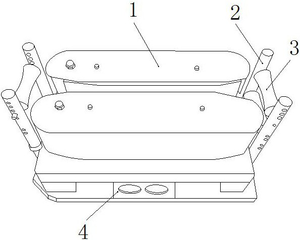
[0024] as attached figure 1 to attach Figure 4 Shown:

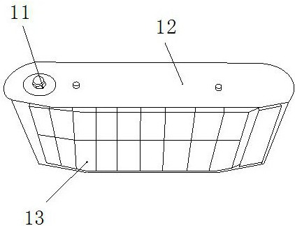
[0025] The present invention provides a cable conveyor, the structure of which includes a conveyor 1, a clamping column 2, a roller 3, and a motor 4. The outer side is welded and connected, and the roller 3 is connected to the inner shaft of the clamping column 2. The transporter 1 includes a rotating shaft 11, a side plate 12, and a clamping belt 13. The rotating shaft 11 is connected to the left end of the side plate 12 by bolts. The side plate 12 is in clearance fit with the outside of the clamping belt 13, and the clamping belt 13 is meshed and connected with the outside of the rotating shaft 11. The shape of the roller 3 is a cylindrical shape that gradually shrinks from the outside to the inside, and the number is two. 1 is distributed symmetrically around the center, supporting the entry and exit and output of the cable to prevent the cable's own weight from pulling the insulation layer.

[0026] Wherein, the c...

Embodiment 2

[0031] as attached Figure 5 to attach Figure 7 Shown:

[0032] Wherein, the touch plate 32d includes a support block d1, a backing plate d2, a connecting shaft d3, and a connecting shaft d4. Side welding connection, the connecting shaft d3 is connected to the left axis of the middle part of the backing plate d2, and the middle connecting shaft d4 is hingedly connected to the left lower end of the backing plate d2, and the number of the backing plates d2 is two, with the middle connecting shaft d4 The center is distributed symmetrically up and down, and forms an angle with an obtuse angle, and the upper and lower offsetting force is applied to the cable, which is beneficial to increase the stress area of ​​the cable surface and reduce the average stress of the cable. Protect the cable insulation layer from cracking .

[0033] Wherein, the support block d1 includes a support plate r1, a fixed shaft r2, a spring plate r3, and a ball r4, the inner side of the support plate r1...


PUM


Abstract

The invention discloses a cable conveyor, which comprises a conveyor, a clamping column, a roller, and a motor. The conveyor is connected with bolts on the upper side of the motor, and the clamping column is welded to the outside of the motor. The cable is fixed and transported by holding the belt. During the transport process, the spring supported by the plate presses the touch plate to protect and transport the cable, which prevents the molecular structure activity of the rubber material of the cable insulation layer from being reduced in cold air, resulting in The deformation caused in the process leads to cracks in the insulating layer and reduces the insulation of the cable. During the process of conveying the cable, the backing plate tightly wraps the cable under the cooperation of the connecting shaft and the connecting shaft, and the deformation of the support block increases the contact area of ​​the cable. Reduce the force per unit area of ​​the insulating layer, prevent the outer insulating layer of the cable from loosening, deforming or even breaking due to excessive traction, ensure the insulation of the cable itself, and prevent leakage hazards.

Description

technical field [0001] The invention belongs to the field of cables, and more specifically, relates to a cable conveyor. Background technique [0002] The cable conveyor is a machine used to install cables during cable laying. In the winter in the north, the climate is cold and dry. During the laying of cables, the outer insulating layer of the cables is made of rubber, and the rubber material has molecules in the cold air. The structural activity is reduced, which will lead to cracks in the insulation layer during the deformation process and reduce the insulation of the cable, and because the conveyor uses belt clamping and traction, excessive traction will cause the outer insulation layer of the cable to loosen, deform or even break. Reduce the insulation of the cable, causing leakage hazards. Contents of the invention [0003] In order to solve the problem that the above technical conveyor adopts belt clamping traction, excessive traction will cause the outer insulatin...

Claims


Application Information

Patent Timeline
Patent Type & Authority Patents(China)
IPC IPC(8): H02G1/06B65H51/14B65H51/08
CPCH02G1/06B65H51/14B65H51/08B65H2701/34
Inventor 方明炎
Owner 山东鹤鹏技术有限公司
Why Eureka
Try Eureka