Magnetic coupling structure and wireless power transmission system

A magnetic coupling and magnetic energy technology, applied in electrical components, circuit devices, etc., can solve the problems of poor coupling performance and low utilization of magnetic cores

Active Publication Date: 2020-10-20
CHINA UNIV OF MINING & TECH
View PDF7 Cites 6 Cited by
  • Summary
  • Abstract
  • Description
  • Claims
  • Application Information

AI Technical Summary

Problems solved by technology

[0004] Technical solution: The present invention proposes a magnetic coupling structure and a wireless power transmission system to solve the technical problems of l...

Method used


Image

  • Magnetic coupling structure and wireless power transmission system
  • Magnetic coupling structure and wireless power transmission system
  • Magnetic coupling structure and wireless power transmission system

Examples


Embodiment 1

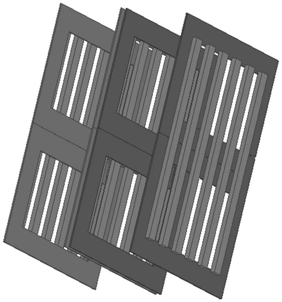
[0031] figure 1 The magnetic coupling structure proposed in Embodiment 1 is shown, including: including a primary side magnetic energy emission structure and a secondary side magnetic energy pickup structure; the primary side magnetic energy emission structure is a double-sided common-core structure, including the first magnetic core layer in the middle and The first coil and the second coil are respectively laid on the front and back of the first magnetic core layer; there are two secondary magnetic energy pick-up structures, which are the front magnetic energy pick-up structure and the reverse magnetic energy pick-up structure, and the two secondary magnetic energy pick-up structures Arranged in parallel on both sides of the primary side magnetic energy emission structure, and two secondary side magnetic energy pick-up structures are respectively coupled and connected to the primary side magnetic energy emission structure; the front magnetic energy pick-up structure includes ...

Embodiment 2

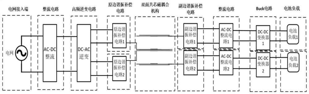
[0036] The present invention also proposes a wireless power transmission system. In this embodiment, the background of electric vehicle charging is substituted, and a wireless power transmission system for electric vehicle charging is proposed, such as figure 2 As shown, it includes: power grid access terminal, primary side AC-DC rectifier device, primary side DC-AC high frequency inverter device, primary side resonant compensation circuit, magnetic coupling mechanism described in Embodiment 1, secondary side resonant compensation circuit , secondary side AC-DC rectification device, DC-DC converter and battery load, among which the primary side AC-DC rectification device and primary side DC-AC high frequency inverter device can be collectively referred to as the primary side power conversion device, and the secondary side AC- DC rectification and DC-DC converter are collectively referred to as secondary power conversion devices.

[0037]In this embodiment, the primary-side DC...


PUM


Abstract

The invention provides a magnetic coupling structure and a wireless electric energy transmission system, the magnetic coupling structure comprises a primary side magnetic energy emission structure andsecondary side magnetic energy pickup structures: the primary side magnetic energy emission structure is a double-sided common core structure and comprises a first magnetic core layer in the middle,and a first coil and a second coil which are respectively laid on the front surface and the back surface of the first magnetic core layer; the number of the secondary side magnetic energy pickup structures is two, the two secondary side magnetic energy pickup structures are a front side magnetic energy pickup structure and a back side magnetic energy pickup structure respectively, the two secondary side magnetic energy pickup structures are arranged on the two sides of the primary side magnetic energy emission structure in parallel, and the two secondary side magnetic energy pickup structuresare in coupling connection with the primary side magnetic energy emission structure respectively. According to the wireless electric energy transmission system, the magnetic coupling structure is applied, the electric energy transmission of the two secondary side electric energy receiving circuits can be achieved only through one magnetic core layer, the use amount of magnetic cores on the coupling mechanism is greatly reduced, and the utilization rate of the magnetic cores and the magnetic coupling efficiency are improved.

Description

technical field [0001] The invention relates to the technical field of wireless power transmission, in particular to a magnetic coupling structure and a wireless power transmission system. Background technique [0002] Wireless power transmission technology is a new mode that completely breaks away from the shackles of wires or cables by means of intangible soft media in space (such as magnetic fields, electric fields, lasers, microwaves, etc.), and realizes wireless power transmission and flexible power access in a complete sense. Greater cleanliness, flexibility and safety are regarded as an important way to achieve clean, flexible and efficient utilization of energy, and have received extensive attention and research from the international community. The traditional wireless power transmission is one-to-one mode, the output power and efficiency of the whole system are low, the magnetic core layer in the primary power transmission coil cannot be fully utilized, and the cou...

Claims


Application Information

Patent Timeline
IPC IPC(8): H02J50/12H02J50/40H02J50/70
CPCH02J50/12H02J50/402H02J50/70
Inventor 夏晨阳杨旭浩李晓丽李壮冯其凯魏楠韩潇左马帅
Owner CHINA UNIV OF MINING & TECH
Why Eureka
Try Eureka