Double-row shaft rod chip mounting head

A technology of patch head and shaft, applied in electrical components, electrical components, etc., can solve problems such as high cost and inability to achieve flexibility

Pending Publication Date: 2020-10-20
广东木几智能装备有限公司
View PDF1 Cites 2 Cited by
  • Summary
  • Abstract
  • Description
  • Claims
  • Application Information

AI Technical Summary

Problems solved by technology

This technical solution, on the one hand, the cost of linear motors is higher than that of stepping motors, and on the other hand, two rotating motors are used to control the rotati

Method used


Image

  • Double-row shaft rod chip mounting head
  • Double-row shaft rod chip mounting head
  • Double-row shaft rod chip mounting head

Examples


Embodiment Construction

[0026] In order to illustrate the technical solution of the present invention more clearly, the following will be introduced in conjunction with the accompanying drawings.

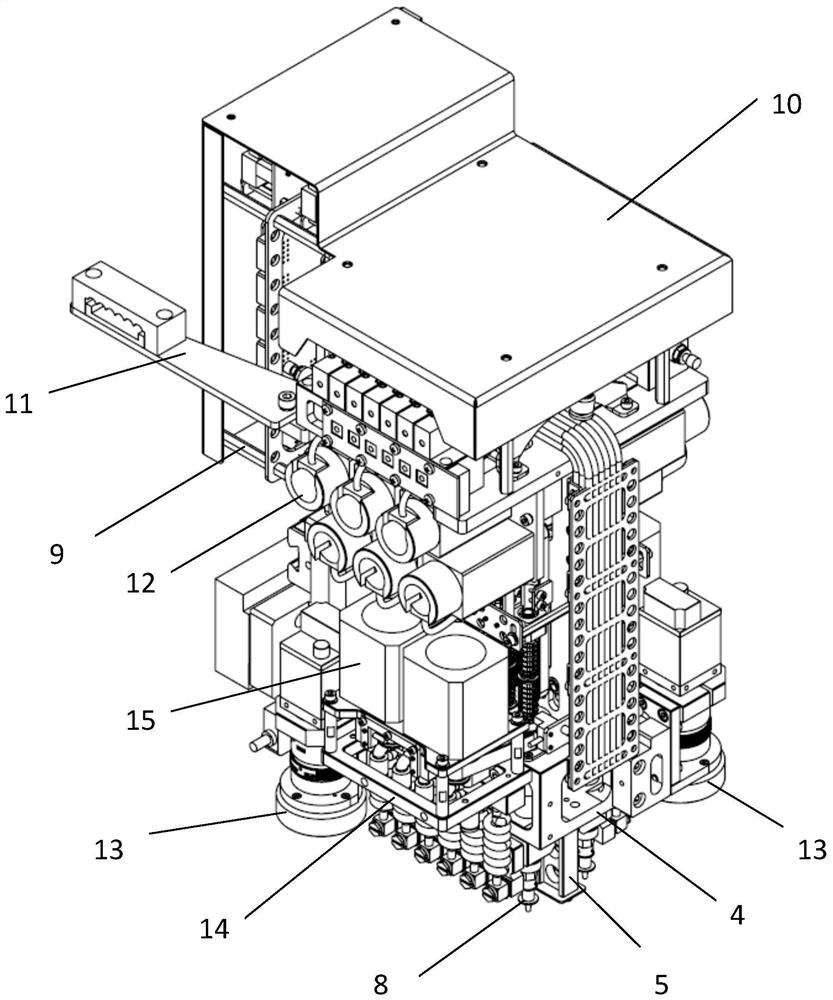
[0027] Such as figure 1 As shown, the main structure of the patch head of the present invention includes a top plate 1, a main side plate 2, a main mounting plate 3, a spline shaft mounting seat 4, a Z-axis guide plate 5, a Z-axis motor mounting seat 6, a spline shaft 7, and a suction nozzle 8. The schematic diagram shows the relative position of the various components. Except that the suction nozzle 8 and the spline shaft 7 are connected by the movable rotating seat of the spline shaft, each part is fastened and connected with bolts.

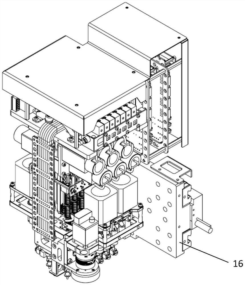
[0028] Such as figure 2 As shown, the patch head card device is composed of a head card mounting bracket 9, a lead bracket 11, and a head cover 10. The chip head control card is installed inside and fixed on the main side plate 2 back.

[0029] Such as figure 2 As sh...


PUM


Abstract

The invention discloses a double-row shaft rod chip mounting head, which is composed of a chip mounting head main body structure, two rows of chip mounting mechanisms, Z-axis motor and synchronizers,R-axis motor and synchronizers, a MARK camera, a chip mounting head clamping device and a chip mounting head bracket, wherein the two rows of chip mounting mechanisms penetrate through a spline shaftmounting seat and are respectively mounted on two sides of a main mounting plate and a Z-axis guide plate; the Z-axis motors are the same as the mounting mechanisms in number, are respectively mountedon two sides of the main mounting plate, and control the chip mounting mechanisms to move up and down through synchronous wheels and synchronous belts; the R-axis motors are installed on the two sides of the spline shaft mounting seat respectively, and each R-axis motor controls the rotating movement of the multiple chip mounting mechanisms through the synchronous wheel and the synchronous belt.The double-row shaft rod chip mounting head has the beneficial effects that as the chip mounting mechanism of the double-row chip mounting head is doubled, the number of suction mounting elements in one stroke is doubled, and the overall chip mounting speed of the chip mounter is nearly doubled; and meanwhile, compared with a linear motor, the cost is lower, the whole machine is miniaturized due to the compact design, and the cost is also reduced.

Description

technical field [0001] The invention relates to a placement head structure of a placement machine, in particular to a placement head with double rows of shaft rods, and belongs to the technical field of placement machines. Background technique [0002] The placement head is the core component of the placement machine. The number and arrangement of the placement mechanism composed of spline shafts and suction nozzles limit the maximum number of components that the placement head can absorb and paste in one stroke. Generally, the placement mechanism of the placement head is distributed in a single row, and the number is 1 to 8, or even 10, but the number is too large, the horizontal dimension of the placement head is wider, and the overall weight is heavier, which limits the number of placement mechanisms to continue to increase. The structural design of double-row patch heads has become a research direction to solve the above problems. [0003] The Chinese patent "A placemen...

Claims


Application Information

Patent Timeline
IPC IPC(8): H05K13/04H05K13/08
CPCH05K13/0406H05K13/0409H05K13/0411H05K13/0812
Inventor 吴志达程治国张金坪
Owner 广东木几智能装备有限公司
Why Eureka
Try Eureka