one-way clutch

A technology for one-way clutches and engaging surfaces, applied in one-way clutches, clutches, automatic clutches, etc., can solve the problems of increased influence, heavy workload, and large number of parts, so as to reduce the number of parts and ease the operation Affordable, easy-to-manufacture effects

Active Publication Date: 2022-04-19
TSUBAKIMOTO CHAIN CO
View PDF11 Cites 0 Cited by
  • Summary
  • Abstract
  • Description
  • Claims
  • Application Information

AI Technical Summary

Problems solved by technology

However, when the inner and outer rings are idling at high speeds, the influence of abrasion of the inner and outer engagement surfaces of the cam becomes greater, so this structure is not suitable for inner and outer rings. One-way clutch used when idling at high speed
[0011] In addition, the one-way clutch has a problem that it is difficult to reduce the size of the one-way clutch in the axial direction due to the urging means that urges the plurality of cams in the inner diameter direction or the outer diameter direction.
In addition, there is also a problem that, when assembling the clutch, a large number of parts are required, resulting in a large workload.

Method used


Image

  • one-way clutch
  • one-way clutch
  • one-way clutch

Examples


Embodiment Construction

[0033] refer to Figure 1-9 Examples of the present invention will be described. However, the present invention is not limited to this embodiment.

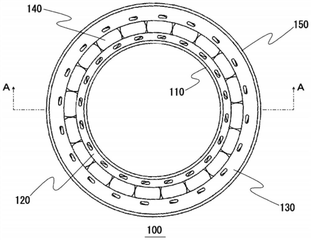
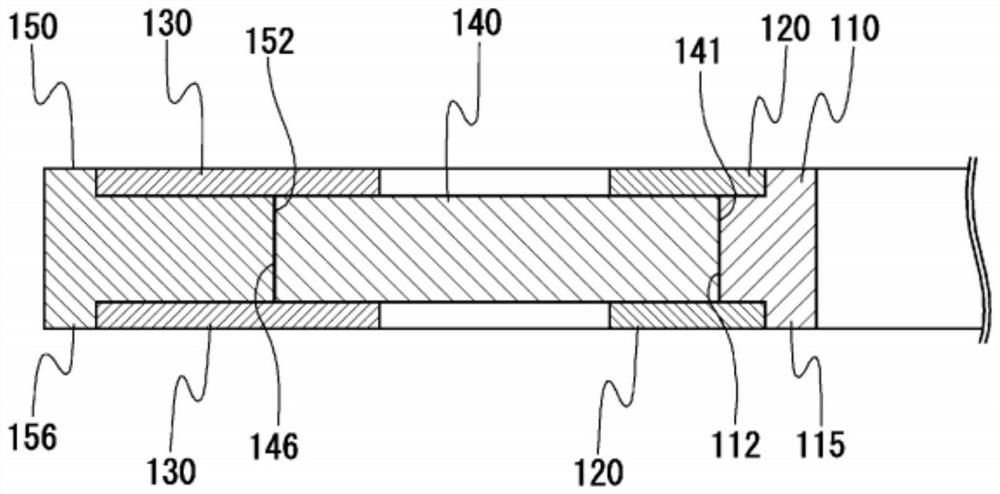
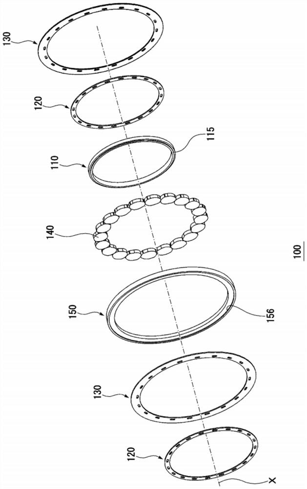
[0034] figure 1 It is a plan view showing a configuration example of the one-way clutch of the present invention. figure 2 yes means figure 1 An enlarged cross-sectional view of a portion of the section on line A-A. image 3 yes figure 1 An exploded perspective view of the one-way clutch shown.

[0035]This one-way clutch 100 includes: an inner ring 110 and an outer ring 150 provided so as to be relatively rotatable on the same X-axis; and a plurality of cams 140 provided between the inner ring 110 and the outer ring 150 .

[0036] Each cam 140 has an inner peripheral engaging surface 141 and an outer peripheral engaging surface 146, and both end surfaces are flat surfaces.

[0037] The inner peripheral engaging surface 141 of the cam 140 is configured to frictionally engage with the outer peripheral engaging surface 112 o...


PUM


Abstract

The present invention provides a one-way clutch, which is simple and easy to manufacture, can be miniaturized in the axial direction, is light in weight and is not easy to be damaged, and can prevent the inner peripheral side engaging surface and the outer peripheral side engaging surface of the cam during high-speed idling wear and tear. Specifically, the one-way clutch of the present invention has: an inner ring (110) and an outer ring (150), which are arranged to be relatively rotatable on the same axis; a plurality of cams (140), which are arranged on the inner ring (110) and In the circumferential direction between the outer ring (150); and the side plates (120), (130), which are arranged on at least one of the inner ring (110) and the outer ring (150), are located on the axis relative to the cam (140). to the sides. Each of the plurality of cams (140) is configured such that when the inner ring (110) and the outer ring (150) rotate in the same direction, they receive a predetermined centrifugal force and move toward each other relative to the inner ring (110) and the outer ring (150). Rotate in the engaging direction.

Description

technical field [0001] The present invention relates to a one-way clutch provided with a plurality of cams between an inner ring and an outer ring and configured so that when the inner ring is rotated in one direction or the outer ring is rotated in the other direction , the engaging surface on the inner peripheral side and the engaging surface on the outer peripheral side of the cam are respectively frictionally engaged with the outer peripheral engaging surface of the inner ring and the inner peripheral engaging surface of the outer ring. When the inner ring is rotated in the other direction or the outer When the ring rotates in one direction, the inner ring or the outer ring performs idle rotation. Background technique [0002] Conventionally, one-way clutches used when the inner and outer rings are idling at high speeds have used cages that hold cams. By holding the cam with a retainer fixed to the inner or outer ring on the high-speed idling side, the cam rotates in th...

Claims


Application Information

Patent Timeline
Patent Type & Authority Patents(China)
IPC IPC(8): F16D41/07F16D43/04
CPCF16D43/04F16D41/07F16D43/18F16D2300/06F16D41/063F16H57/0473
Inventor 岛中祐仁
Owner TSUBAKIMOTO CHAIN CO
Why Eureka
Try Eureka