
Polishing solution applicator and polishing device

A technology of polishing liquid and dispenser, which is applied in the direction of grinding device, grinding driving device, grinding/polishing equipment, etc., which can solve the problem that the continuity and high efficiency of the polishing liquid cannot be guaranteed, the polishing liquid cannot flow in all in time, and the polishing liquid Waste and other issues

Inactive Publication Date: 2020-10-23
INST OF MICROELECTRONICS CHINESE ACAD OF SCI +1
View PDF16 Cites 5 Cited by
  • Summary
  • Abstract
  • Description
  • Claims
  • Application Information

AI Technical Summary

Problems solved by technology

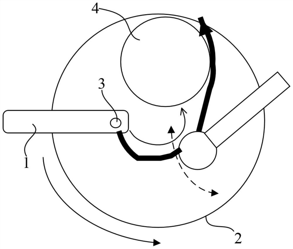
However, due to the use of existing technologies such as figure 1 During the mode, the nozzle 3 is fixedly connected with the transfer arm 1, so that the polishing liquid sprayed by the nozzle 1 is only dispersed to a relatively fixed area of ​​the polishing pad 2, so that the polishing liquid on the fixed area of ​​the polishing pad 2 is more, The sprayed polishing liquid cannot flow into the microporous structure and groove structure on the surface of the polishing pad 2 in time, so that this part of the polishing liquid is thrown out of the polishing pad 2 by the rotating polishing pad 2
Thereby causing a large amount of waste of polishing liquid, can not guarantee the continuity and high efficiency of supplying the polishing liquid amount to the area between wafer and polishing pad 2

Method used


Image

  • Polishing solution applicator and polishing device
  • Polishing solution applicator and polishing device
  • Polishing solution applicator and polishing device

Examples


Embodiment Construction

[0028] In order to make the purpose, technical solutions and advantages of the embodiments of the present invention clearer, the technical solutions in the embodiments of the present invention will be clearly and completely described below in conjunction with the drawings in the embodiments of the present invention. Obviously, the described embodiments It is only some embodiments of the present invention, but not all embodiments. Based on the embodiments of the present invention, all other embodiments obtained by persons of ordinary skill in the art without making creative efforts belong to the protection scope of the present invention.

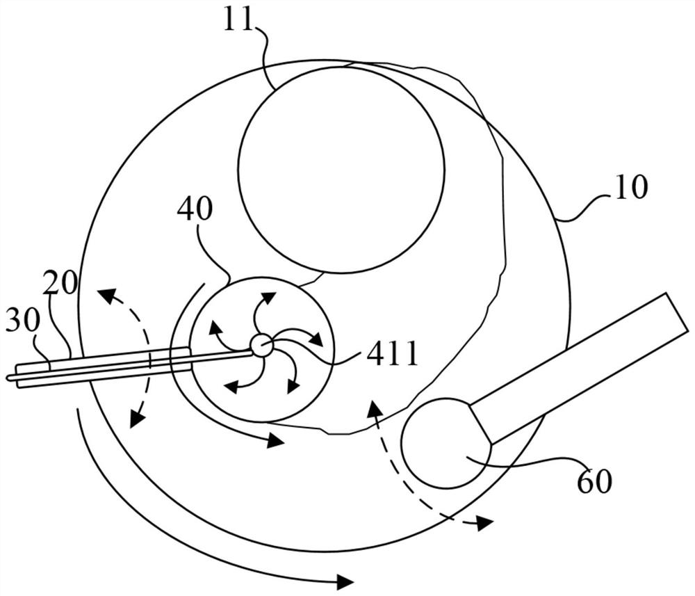
[0029] In order to facilitate the understanding of the polishing liquid dispenser provided by the embodiment of the present invention, the application scene of the polishing liquid dispenser provided by the embodiment of the present invention is firstly described below. The polishing liquid dispenser is used in the process of polishing wafers ...


PUM


Abstract

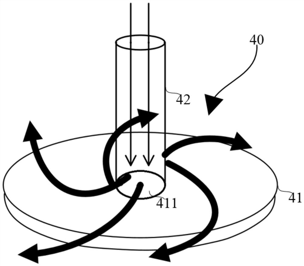
The invention provides a polishing solution applicator and a polishing device. The polishing solution applicator is used for applying a polishing solution to a polishing pad. The polishing solution applicator comprises a supporting arm on the upper side of the polishing pad, and a solution conveying pipe fixed to the supporting arm and used for conveying the polishing solution. The polishing solution applicator further comprises a sprayer which is communicated with the solution conveying pipe and spraying the polishing solution to the surface of the polishing pad. The sprayer is rotationally connected with the supporting arm, and the sprayer is perpendicular to the surface of the polishing pad relates to the rotation direction of the supporting arm. The polishing solution applicator further comprises a driving device for driving the sprayer to rotate relative to the supporting arm. Through the rotating connection of the sprayer and the supporting arm, the driving device drives the sprayer to rotate relative to the supporting arm, the polishing solution sprayed by the sprayer can directly fall and also can rotate, and therefore, the area that the polishing solution is sprayed to thesurface of the polishing pad is increased. The polishing solution more quickly flows into the structures, such as tiny holes and grooves, in the surface of the polishing pad, and a smaller amount ofthe polishing solution is thrown out by the rotating polishing pad, and the amount of the polishing solution flowing into the area between a wafer and the polishing pad is ensured.

Description

technical field [0001] The invention relates to the technical field of semiconductor manufacturing, in particular to a polishing liquid dispenser and a polishing device. Background technique [0002] In a CMP (Chemical Mechanical Polishing, chemical mechanical polishing) process, a polishing liquid is a core material in the CMP process. Therefore, the continuity and high efficiency of the amount of polishing liquid supplied between the polishing pad and the wafer are very important factors in the CMP process. [0003] In the prior art, the structure for spraying polishing liquid on the surface of the polishing pad is as follows: figure 1 As shown, it includes a transfer arm 1 on which a spray head 3 for spraying polishing liquid onto a polishing pad 2 is arranged. And the spray head 3 is fixedly connected with the conveying arm 1, so that the spray head 3 on the conveying arm 1 is stationary relative to the conveying arm. The spray head 3 sprays the polishing liquid onto ...

Claims


Application Information

Patent Timeline
IPC IPC(8): B24B37/04B24B37/26B24B37/34B24B47/00B24B57/02
CPCB24B37/04B24B37/26B24B37/34B24B47/00B24B57/02
Inventor 丁彦荣张月卢一泓刘青
Owner INST OF MICROELECTRONICS CHINESE ACAD OF SCI
Learn More