Supercharge Your Innovation With Domain-Expert AI Agents!

Flexible power head and processing device

A power head, flexible technology, used in grinding drives, metal processing equipment, manufacturing tools, etc., can solve problems such as easy overcutting and workpiece scrapping

Pending Publication Date: 2020-10-23
德屹智能科技(扬州)有限公司
View PDF9 Cites 0 Cited by
  • Summary
  • Abstract
  • Description
  • Claims
  • Application Information

AI Technical Summary

Problems solved by technology

[0005] The technical problem to be solved by the present invention is to provide a flexible power head and a processing device to solve the problem that the existing power spindle is rigidly connected, and it is easy to overcut and cause the workpiece to be scrapped

Method used


Image

  • Flexible power head and processing device
  • Flexible power head and processing device

Examples


Embodiment 1

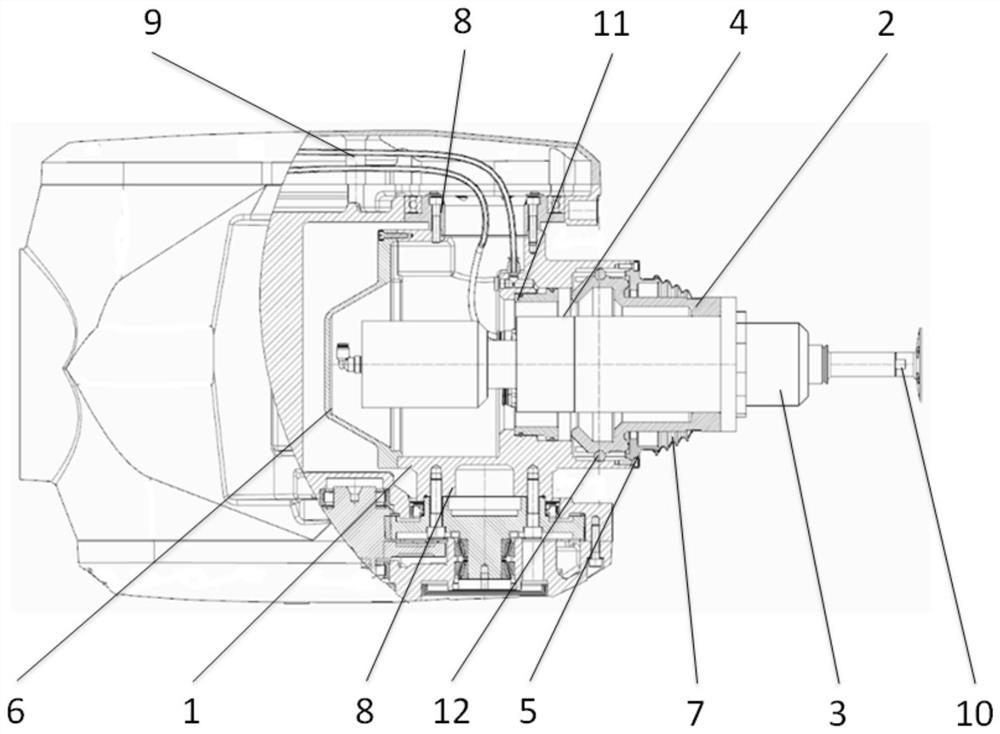
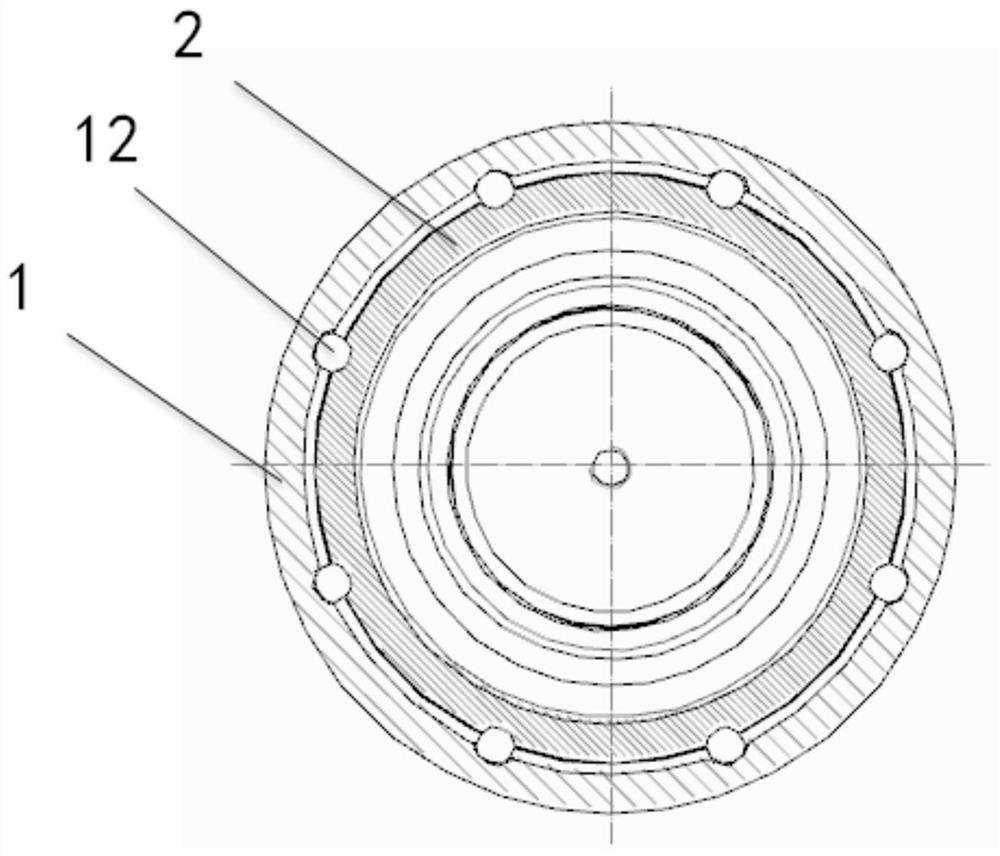
[0034] see figure 1 and figure 2 , In one embodiment, a flexible power head includes a housing 1 , a main shaft installation sleeve 2 , an axial telescopic portion, a movable fulcrum 12 , and a power main shaft 3 .

[0035] The casing 1 is provided with a connecting portion for connecting to an external device, and a first opening of the casing 1 is opened. A first limiting member for limiting the axial displacement of the spindle mounting sleeve 2 to the outside of the housing 1 is provided on the inner wall of the housing 1 .

[0036] The power spindle 3 is fixedly connected to the spindle installation sleeve 2 , and the output end of the power spindle 3 protrudes from the first opening of the casing 1 . The main shaft installation sleeve 2 is movably arranged in the casing 1 . The first axial end of the main shaft installation sleeve 2 is provided with a second limiting member for contacting the first limiting member. In the limiting state, the second limiting member i...

Embodiment 2

[0049] A processing device is equipped with the flexible power head in the first embodiment above.

[0050] In this embodiment, the end of the actuator of the processing device is stably connected to the connecting bumps 8 on both sides of the flexible power head, which avoids the disadvantage of insufficient stability caused by only one end connection in the prior art, and has stronger stability . At the same time, when the tool 10 at the front end of the power spindle 3 of the flexible power head is stressed beyond the pressing force of the top support member 4 on the spindle installation sleeve 2, the spindle installation sleeve 2 will take the movable fulcrum 12 corresponding to the direction of the force as the fulcrum After the swing, the main shaft installation sleeve 2 pushes the support member 4 to move backward to realize the flexible function; when the external force is removed, the support member 4 pushes the main shaft installation sleeve 2 to return to the initia...


PUM


Abstract

The invention discloses a flexible power head and a processing device. A movable spindle mounting sleeve is arranged in a housing. A power spindle is installed on the spindle mounting sleeve. A firstend of the spindle mounting sleeve in the axial direction is in contact with the housing. The flexible power head is also provided an axial telescopic part. The axial telescopic part is used to support a second end of the spindle mounting sleeve in the axial direction. A movable fulcrum piece is arranged between the spindle mounting sleeve and the housing. When radial force applied to a tool at the front end of the power spindle exceeds pressing force of the axial telescopic part on the spindle mounting sleeve, the spindle mounting sleeve swings with the movable fulcrum piece as a fulcrum. When axial force received by the tool exceeds the pressing force of the axial telescopic part on the spindle mounting sleeve, the spindle mounting sleeve pushes the axial telescopic part to move backwardto realize axial and radial flexibility; when external force is eliminated, the axial telescopic part pushes the spindle mounting sleeve to return to an initial position. Flexible connection of the power spindle is realized, and the problems that an existing rigid connection of the power spindle is easily connected and the workpiece is scrapped due to over-cutting are solved.

Description

technical field [0001] The invention belongs to the technical field of mechanical processing, and in particular relates to a flexible power head and a processing device. Background technique [0002] Existing casting automatic grinding devices usually have two forms, one is a CNC machine tool structure, most of the motion axes are linear motion; the other is a robot structure, often using a six-axis industrial robot plus a grinding tool. [0003] What is used to drive the tool to rotate is the power spindle arranged at the end of the CNC machine tool or robot structure. The power spindle is a power component that can realize the main movement and has the function of automatic workpiece circulation. It can be a variable speed transmission mechanism in various forms. The basic principle is that the motor drives a gear transmission mechanism, or the motor directly drives the tool to rotate, which can realize functions such as grinding, boring, milling, and drilling. [0004] ...

Claims


Application Information

Patent Timeline
IPC IPC(8): B24B41/00B24B41/04B24B47/12B24B47/14B24B27/00
CPCB24B41/00B24B41/04B24B47/12B24B47/14B24B27/00B24B27/0092
Inventor 邓念皓易昌
Owner 德屹智能科技(扬州)有限公司
Features
  • R&D
  • Intellectual Property
  • Life Sciences
  • Materials
  • Tech Scout
  • Unparalleled Data Quality
  • Higher Quality Content
  • 60% Fewer Hallucinations
Learn More