Clamping device for three-way pipe connector

A technology for clamping devices and tee pipes, which is applied in the direction of workpiece clamping devices, pipes/pipe joints/fittings, pipes, etc., which can solve the problems of irregular end faces of tee pipe joints, increased difficulty in end face processing, and high cost.

Inactive Publication Date: 2020-10-23
南京江宁区上峰国银标准件厂
View PDF5 Cites 1 Cited by
  • Summary
  • Abstract
  • Description
  • Claims
  • Application Information

AI Technical Summary

Problems solved by technology

[0002] The existing clamping devices for tee pipe joints generally use a bench vise to clamp the tee pipe joints, but in some special occasions, such as when changing the tee pipe joints, due to The three-way pipe joint and the steel pipe are rusted to death, and disassembly is quite difficult. The separation of the three-way pipe joint and the steel pipe is realized by flame cutting at one end, but the end faces of the three-way pipe joints cut in this way are all irregular. Moreover, the end face of the three-way pipe joint is flame-cut, and the hardness will increase, so that the processing difficulty of the end face will become larger, and the existing bench vise cannot effectively realize this type of three-way pipe joint. The clamping is easy to cause the three-way pipe to fly out, the tool to be damaged, etc., the cost is too high

Method used


Image

  • Clamping device for three-way pipe connector
  • Clamping device for three-way pipe connector
  • Clamping device for three-way pipe connector

Examples


Embodiment Construction

[0026] The present invention is described in further detail now in conjunction with accompanying drawing. These drawings are all simplified schematic diagrams, which only illustrate the basic structure of the present invention in a schematic manner, so they only show the configurations related to the present invention.

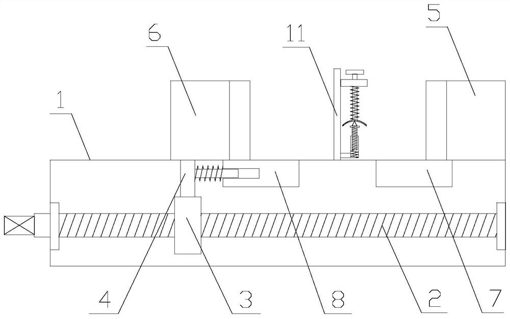
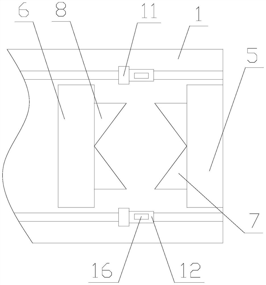
[0027] like Figure 1-4 As shown, a clamping device for three-way pipe joints includes a base 1, a driving mechanism, a clamping mechanism and a limit mechanism, the base 1 is horizontally arranged, the driving mechanism is arranged in the base 1, and the Both the clamping mechanism and the limiting mechanism are arranged on the base 1;

[0028] The driving mechanism includes a first screw rod 2 and a travel ring 3, one end of the first screw rod 2 is arranged on one side of the base 1, and the other end of the first screw rod 2 is arranged in the base 1, so The first screw mandrel 2 is arranged horizontally, the moving ring 3 is sleeved on the first screw m...


PUM


Abstract

The invention relates to a clamping device for a three-way pipe connector. The clamping device comprises a base, a driving mechanism, a clamping mechanism and limiting mechanisms. The driving mechanism comprises a first screw rod and a shifting ring; the clamping mechanism comprises a connecting plate, a first clamping block, a second clamping block, a first V-shaped block and a clamping assembly;and each limiting mechanism comprises a moving rod, a supporting assembly and an abutting assembly. According to the clamping device for the three-way pipe connector, primary clamping for the three-way pipe connector is achieved through the first clamping block and the second clamping block, secondary clamping for the three-way pipe connector is achieved through the first V-shaped block and a second V-shaped block, elastic clamping for the three-way pipe connector is achieved through clamping units, positioning for the three-way pipe connector is achieved at the same time, thus, two end openings in the same axis are parallel, and then, limiting and supporting for the two parallel end openings are achieved through the limiting mechanisms. In this way, the stability of the three-way pipe connector is maintained during end face machining, so that machining is stable, and the use practicality is improved.

Description

technical field [0001] In particular, the invention relates to a clamping device for a three-way pipe joint. Background technique [0002] The existing clamping devices for tee pipe joints generally use a bench vise to clamp the tee pipe joints, but in some special occasions, such as when changing the tee pipe joints, due to The three-way pipe joint and the steel pipe are rusted to death, and disassembly is quite difficult. The separation of the three-way pipe joint and the steel pipe is realized by flame cutting at one end, but the end faces of the three-way pipe joints cut in this way are all irregular. Moreover, the end face of the three-way pipe joint is flame-cut, and the hardness will increase, so that the processing difficulty of the end face will become larger, and the existing bench vise cannot effectively realize this type of three-way pipe joint. The clamping is easy to cause the three-way pipe to fly out, the tool to be damaged, etc., which is too high in cost. ...

Claims


Application Information

Patent Timeline
Patent Type & Authority Applications(China)
IPC IPC(8): B25B11/00F16L41/02
CPCB25B11/00F16L41/02
Inventor 韩平
Owner 南京江宁区上峰国银标准件厂
Why Eureka
Try Eureka