Rotating mold for rotational moulding continuous forming

A rotary and mold technology, applied in the direction of coating, etc., can solve the problems of poor stability, inability to perform injection molding at the same time, defective products, etc.

Active Publication Date: 2020-10-23
东莞市力图塑胶制品有限公司
View PDF7 Cites 0 Cited by
  • Summary
  • Abstract
  • Description
  • Claims
  • Application Information

AI Technical Summary

Problems solved by technology

[0002] The mold is a tool for forming blanks into specific shapes and sizes under the action of external force. It is widely used in the fields of mechanical parts manufacturing, rubber, and ceramics manufacturing. It melts raw materials into liquid at high temperature, and then injects the liquid into the mold. After cooling, it forms The method of product is also one of the methods of mold production, but the existing technology adopts the method of controlling the injection volume by setting the injection time, which has poor stability and cannot guarantee that the injection liquid can fill the mold with each injection, and it needs to be watched repeatedly. The way of injection molding at injection molding time is easily affected by the change of flow rate and density of injection molding liquid, so that the injection liquid cannot fill the mold, resulting in the appearance of defective products, and the existing mold injection molding production cannot perform injection molding, cooling, and removal at the same time Product operation, so that the production efficiency can not be effectively improved, so people need rotary mold for continuous molding to solve the above problems

Method used


Image

  • Rotating mold for rotational moulding continuous forming
  • Rotating mold for rotational moulding continuous forming
  • Rotating mold for rotational moulding continuous forming

Examples


Embodiment

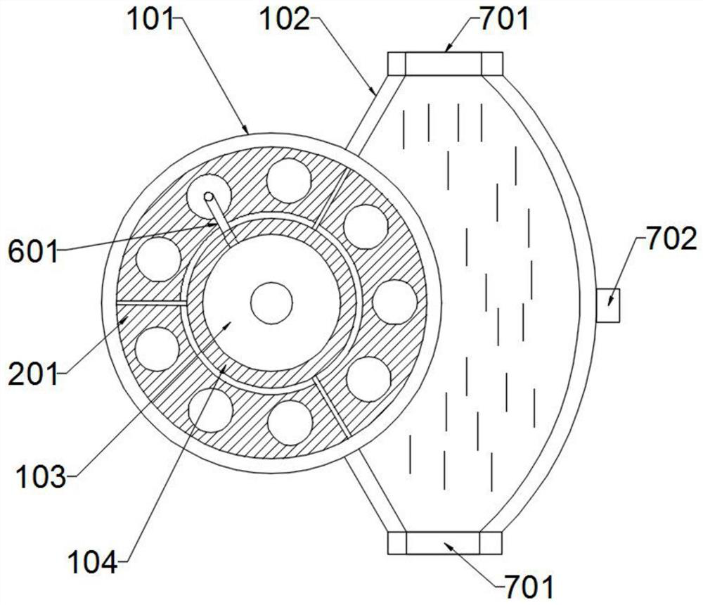
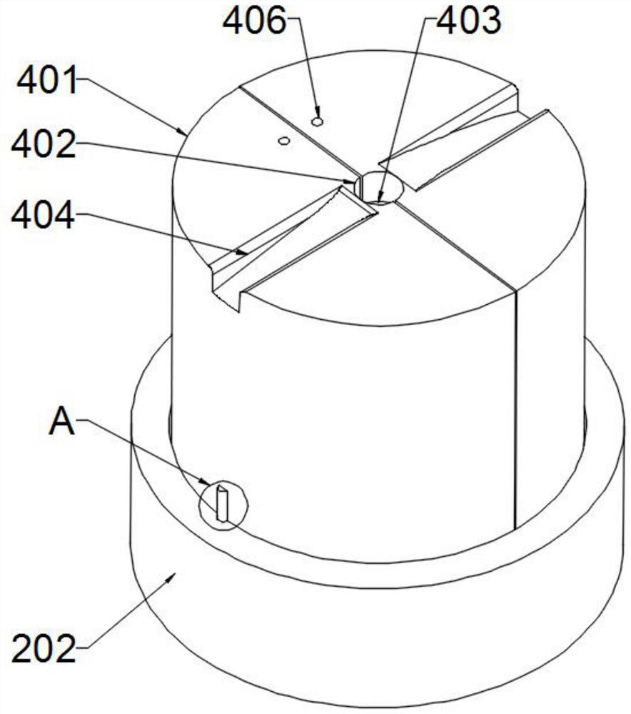
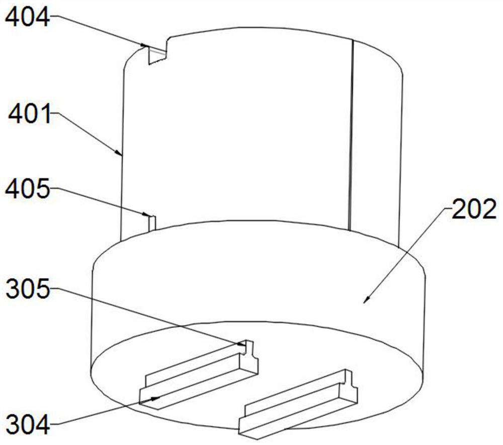
[0027] Example: such as Figure 1-7 As shown, the rotary mold for rotomolding continuous molding includes a support component, a rotating fixed component, an elastic component, a forming component, an isolation component, a pass-through component, and a cooling component. For the function of other components, there is a rotating and fixing component above the support component, which plays the role of controlling the movement of the mold, and an elastic component is arranged under the rotating and fixing component, which controls the small elastic displacement of the mold. There is a forming component on the component, the forming component plays the role of completing the basic mold shaping operation, an isolation component is arranged above the rotating fixed component, and the isolating component plays the role of partitioning the rotating fixed component, and the supporting component is provided with a through-close Components, the opening and closing components play the r...


PUM


Abstract

The invention discloses a rotating mold for rotational moulding continuous forming and belongs to the technical field of mold product production. The rotating mold comprises a supporting assembly, a rotary fixing assembly and an elastic assembly. The supporting assembly is located at the lowest end of the whole device. The rotary fixing assembly is arranged above the supporting assembly. The elastic assembly is arranged below the rotary fixing assembly. The rotating mold is scientific, reasonable, and safe and convenient to use. According to the device, a liquid blocking piece is utilized forcontrolling on-off of injection molding liquid, a spring is utilized for enabling a cambered surface fitting pipe to break away from an injection molding hole in time after injection molding is full,and the function of stopping injection molding automatically after injection molding is completed is achieved. Compared with the existing manner of making injection molding time for controlling the injection molding amount, the stability is possessed, it can be ensured that the mold is filled with the injection molding liquid for each time of injection molding, the manner adopting for controllinginjection molding time for injection molding is influenced easily by the change of flow speed and concentration of the injection molding liquid, the injection molding liquid cannot fill the mold fully, occurrence of defective goods is caused, and the device can effectively improve quality of products produced through the mold.

Description

technical field [0001] The invention relates to the technical field of mold product production, in particular to a rotary mold for continuous molding of rotational molding. Background technique [0002] The mold is a tool for forming blanks into specific shapes and sizes under the action of external force. It is widely used in the fields of mechanical parts manufacturing, rubber, and ceramics manufacturing. It melts raw materials into liquid at high temperature, and then injects the liquid into the mold. After cooling, it forms The method of product is also one of the methods of mold production, but the existing technology adopts the method of controlling the injection volume by setting the injection time, which has poor stability and cannot guarantee that the injection liquid can fill the mold with each injection, and it needs to be watched repeatedly. The way of injection molding at injection molding time is easily affected by the change of flow rate and density of injecti...

Claims


Application Information

Patent Timeline
IPC IPC(8): B29C41/38B29C41/04B29C41/46B29C41/34
CPCB29C45/2602B29C45/2681B29C45/581B29C45/73B29C45/7613
Inventor 唐箫
Owner 东莞市力图塑胶制品有限公司
Why Eureka
Try Eureka