Rear door automatic elevator for electric vehicle

An automatic lift, electric vehicle technology, applied in the arrangement, transportation and packaging of vehicle parts, pedals or ladders, etc., can solve the problems of not having electric lifts, affecting the efficiency of handling, convenient use, inconvenient to transfer goods up and down, etc.

Pending Publication Date: 2020-10-23
安徽双鹿车业有限公司
View PDF0 Cites 1 Cited by
  • Summary
  • Abstract
  • Description
  • Claims
  • Application Information

AI Technical Summary

Problems solved by technology

[0002] With the continuous development of new energy technology, electric vehicles are gradually entering the homes of ordinary users. Many electric vehicles do not have electric lifts on the back doors, especially some pickup trucks. The body is much higher than that of a car. It is very inconvenient to load goods in the rear compartment, which is inconvenient to move up and down. It directly affects the efficiency of handling and convenient daily use. Therefore, a rear door automatic elevator for electric vehicles is designed here to solve the above problems.

Method used


Image

  • Rear door automatic elevator for electric vehicle
  • Rear door automatic elevator for electric vehicle
  • Rear door automatic elevator for electric vehicle

Examples


Embodiment 1

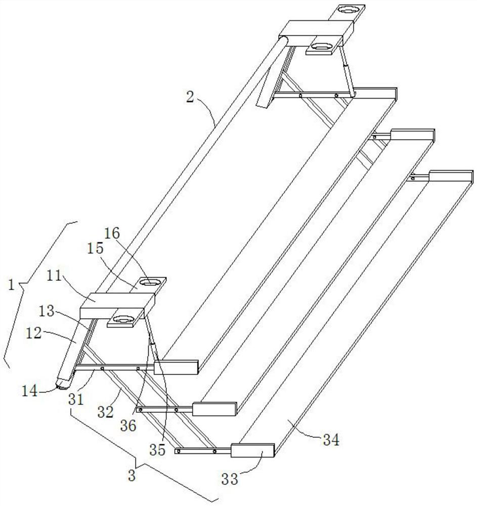
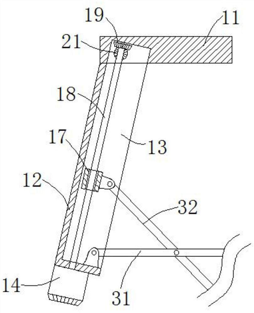
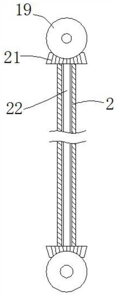
[0023] see Figure 1-3 , the present embodiment provides an automatic rear door elevator for electric vehicles, including two installation support mechanisms 1, two stepping mechanisms 3 and transmission sleeves 2, and the two installation support mechanisms 1 include installation plates 11 and adjustment plates 12. The two installation support mechanisms 1 are distributed front and back, and the left ends of the opposite side walls of the two installation plates 11 are fixedly plugged with the axial ends of the drive sleeve 2 respectively, and each adjustment plate 12 is welded on the On the left side of the bottom end surface of each mounting plate 11 , the two pedaling mechanisms 3 each include a plurality of first articulated rods 31 , a plurality of second articulated rods 32 and a plurality of mounting back plates 33 .

[0024] The right end surface of each adjustment plate 12 is provided with an adjustment groove 13 extending to the inner cavity of each corresponding in...

Embodiment 2

[0030] see Figure 1-3 , further improvements have been made on the basis of Example 1:

[0031] The front and rear sides of the right end of each mounting plate 11 are fixedly provided with extension plates 15, and each extension plate 15 is provided with mounting holes 16, and the mounting holes 16 of each extending plate 15 are penetrated by bolts to facilitate the installation of the mounting plate 11. Fixed installation.

[0032] Two installation backboards 33 on the uppermost side are hinged with telescopic sleeves 35 on the left side of the opposite side wall through pin shafts, and the tops of the two telescopic sleeves 35 are slidingly inserted with T-shaped telescopic rods 36, and two T-shaped telescopic rods 36 The top of the top is respectively hinged with the right side of the bottom end face of the two mounting plates 11, and the telescopic sleeve 35 inner cavity is free to expand and contract by the T-shaped telescopic rod 36, which can enhance the hoisting sta...


PUM


Abstract

The invention discloses a rear door automatic elevator for an electric vehicle, which comprises two mounting and supporting mechanisms, two treading mechanisms and a transmission sleeve, wherein eachof the two mounting and supporting mechanisms comprises a mounting plate and an adjusting plate; the two mounting and supporting mechanisms are distributed front and back. And the left ends of the opposite side walls of the two mounting plates are fixedly connected with the two axial ends of the transmission sleeve in an inserted mode correspondingly, each adjusting plate is welded to the left side of the bottom end face of the corresponding mounting plate in the mode of inclining leftwards and downwards by 60 degrees, and the two treading mechanisms each comprise a plurality of first hinge rods, a plurality of second hinge rods and a plurality of mounting back plates. The mounting plates of the two mounting and supporting mechanisms are fixedly mounted below the rear door of the electricvehicle, and goods can be conveniently transferred and carried up and down by stretching and retracting the pedal between the two treading mechanisms at any time.

Description

technical field [0001] The invention relates to the related technical field of an automatic rear door elevator for an electric vehicle, in particular to an automatic rear door elevator for an electric vehicle. Background technique [0002] With the continuous development of new energy technology, electric vehicles are gradually entering the homes of ordinary users. Many electric vehicles do not have electric lifts on the back doors, especially some pickup trucks. The body is much higher than that of a car. General goods It is very inconvenient to load goods in the rear compartment, which is inconvenient to transfer up and down. It directly affects the efficiency of handling and convenient daily use. Therefore, a rear door automatic lift for electric vehicles is designed here to solve the above problems. Contents of the invention [0003] The object of the present invention is to provide an automatic lift for the rear door of an electric vehicle to solve the problems raised...

Claims


Application Information

Patent Timeline
IPC IPC(8): B60R3/02
CPCB60R3/02
Inventor 李建忠
Owner 安徽双鹿车业有限公司
Why Eureka
Try Eureka