A sewage purification device that can control biotechnology

A technology of sewage purification and biotechnology, applied in the field of sewage purification, can solve the problems of reducing the biological treatment effect, reducing the growth of biofilm, etc., to achieve the effect of improving the treatment effect, reducing the limit of edges and corners, and being easy to fall

Active Publication Date: 2022-03-25
云锦华彰(北京)生物科技有限公司
View PDF0 Cites 1 Cited by
  • Summary
  • Abstract
  • Description
  • Claims
  • Application Information

AI Technical Summary

Problems solved by technology

[0003] Due to the impurities in the sewage, during the aeration treatment at the bottom, the impurities will float upwards with the push of the gas and contact with the biological filler, and the bottom gas will continue to blow upwards, and the impurities will form a relative balance with the biological filler, resulting in Impurities get stuck on the bio-media, reducing the growth of biofilm on the bio-media, thereby reducing the effectiveness of the biological treatment

Method used


Image

  • A sewage purification device that can control biotechnology
  • A sewage purification device that can control biotechnology
  • A sewage purification device that can control biotechnology

Examples


Embodiment 1

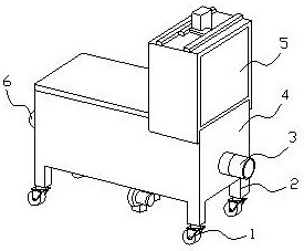
[0028] Example 1: Please refer to Figure 1-Figure 6 , the specific embodiment of the present invention is as follows:

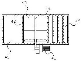
[0029] Its structure includes caster 1, support column 2, drain pipe 3, sewage purification structure 4, case 5, and water inlet pipe 6. The caster 1 is installed at the lower end of the support column 2 and is movably connected, and the support column 2 is vertically installed on the The four corners of the lower end of the sewage purification structure 4 are welded to each other, the drain pipe 3 runs through the inner side of the right end of the sewage purification structure 4 and communicates with each other, the chassis 5 is horizontally installed on the upper end of the sewage purification structure 4 and is mechanically connected, and the water inlet pipe 6 is embedded It is installed on the left end of the sewage purification structure 4 and connected to each other; the sewage purification structure 4 includes a sedimentation tank 41, a partition 42...

Embodiment 2

[0036] Example 2: Please refer to Figure 4 , Figure 7 , Figure 8 , the specific embodiment of the present invention is as follows:

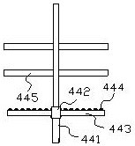
[0037] The packing rack 445 includes a support rod 45a, a linkage structure 45b, a plug 45c, and a frame body 45d. The linkage structure 45b is fixedly installed on the outside of the support rod 45a and is clamped. The frame body 45d is mechanically connected, and the frame body 45d is hingedly connected to the outside of the linkage structure 45b.

[0038] see Figure 7 , the frame body 45d includes a connecting groove d1, a rod body d2, an arc rod d3, and a carrier d4, the connecting groove d1 is recessed at the inner bottom end of the rod body d2, and the arc rod d3 is installed between the rod bodies d2 and is mechanically connected, The carrier d4 is embedded in the inner side of the arc rod d3 and is connected movably to form a uniform distribution of the carrier, which is convenient for the biofilm to fall off.

[0039] see Figu...


PUM


Abstract

The invention discloses a biotechnologically controllable sewage purification device, the structure of which comprises casters, support columns, drainage pipes, sewage purification structures, cabinets, and water inlet pipes. The support columns are vertically installed at the four corners of the lower end of the sewage purification structure, and the drainage pipes run through On the inner side of the right end of the sewage purification structure, the chassis is horizontally installed on the upper end of the sewage purification structure, and the water inlet pipe is embedded and installed on the left end of the sewage purification structure. The sewage purification structure includes a sedimentation tank, a partition, a biological treatment chamber, an aeration structure, a blower, and a filter chamber. An aeration structure is installed inside the biological treatment chamber. While the biofilm is concentrated for treatment, the inclined surface prevents the impurities from forming a relative balance and staying, which facilitates the growth of the biofilm and improves the sewage treatment effect; A frame is set on the outside of the linkage structure, which reduces the restrictions on the edges and corners on the inside, making it difficult for impurities to be stuck on the inside, thereby ensuring the growth of biofilm and better biological treatment of sewage.

Description

technical field [0001] The invention belongs to the field of sewage purification, and specifically relates to a sewage purification device capable of controlling biological technology. Background technique [0002] Sewage is usually the sewage produced by people in daily production activities and the sewage produced in industrial production, and the random discharge of sewage will pollute the water source and soil, so it is necessary to purify the sewage, and there are many purification treatment methods for sewage, among which Including biological treatment, the chlorine in sewage is treated by aeration treatment, and in order to better purify sewage, a sewage purification device that can control biological technology is derived, but the existing technology has the following shortcomings: [0003] Due to the impurities in the sewage, during the aeration treatment at the bottom, the impurities will float upward with the push of the gas and contact with the biological filler,...

Claims


Application Information

Patent Timeline
Patent Type & Authority Patents(China)
IPC IPC(8): C02F9/14
CPCC02F9/00C02F2001/007C02F1/001C02F3/02C02F2201/002C02F2203/006
Inventor 陈刚
Owner 云锦华彰(北京)生物科技有限公司
Why Eureka
Try Eureka