
Riverway water pollution floating garbage cleaning device

A technology for garbage cleaning and water pollution. It is used in the cleaning of open water surfaces, water conservancy projects, filtration and separation, etc. It can solve the problem of manual salvage and labor consumption.

Active Publication Date: 2020-10-23
宁夏鸿辉建筑工程有限公司
View PDF8 Cites 6 Cited by
  • Summary
  • Abstract
  • Description
  • Claims
  • Application Information

AI Technical Summary

Problems solved by technology

[0004] The purpose of the present invention is to solve the shortcomings of manual salvage and large manpower consumption in the prior art, and propose a river channel water pollution floating garbage cleaning device

Method used


Image

  • Riverway water pollution floating garbage cleaning device
  • Riverway water pollution floating garbage cleaning device
  • Riverway water pollution floating garbage cleaning device

Examples


Embodiment 1

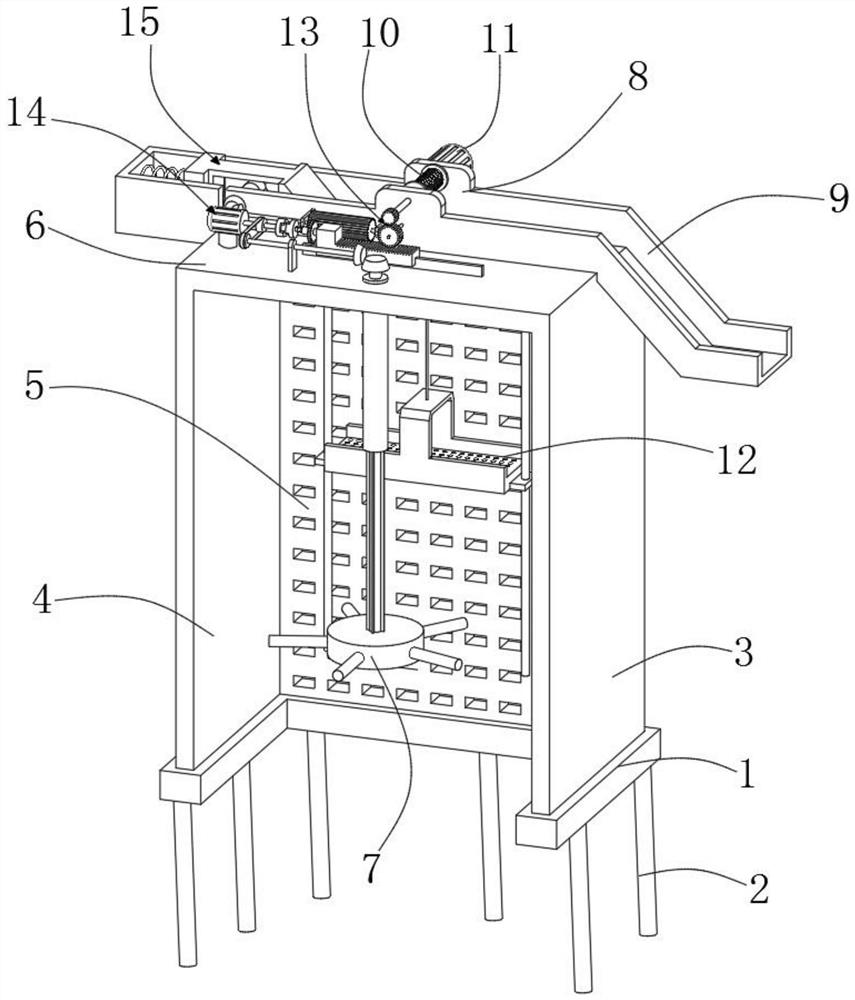
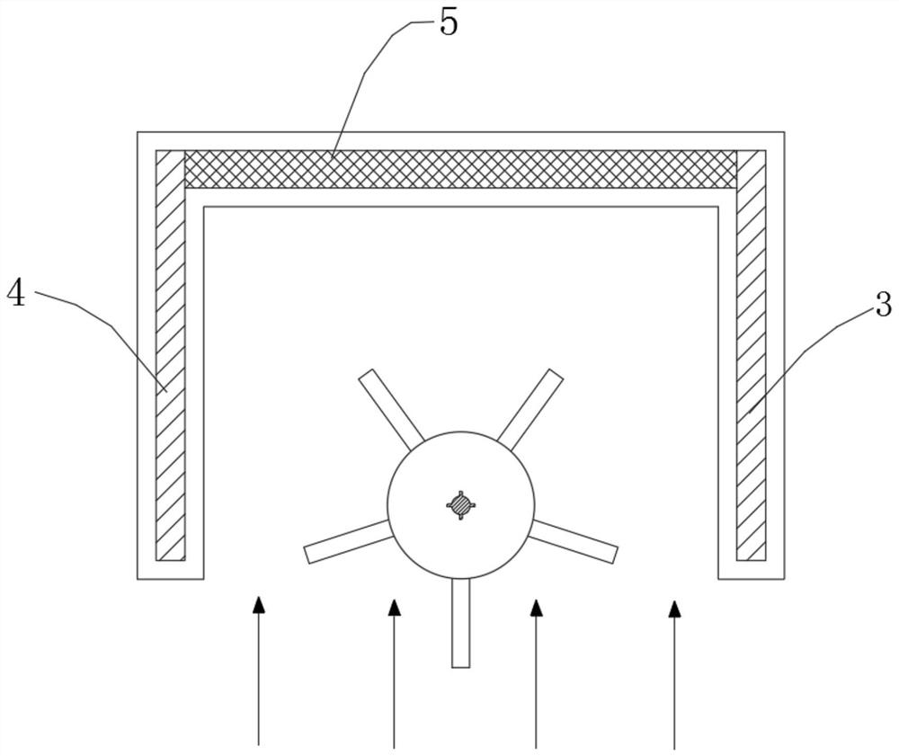
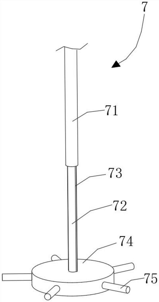
[0031] refer to Figure 1-4, a kind of river course water pollution floating rubbish cleaning device, comprises base 1, and the bottom of base 1 is fixedly installed with several support columns 2, and support column 2 is the concrete cylinder poured on the bottom of river downstream; The top side of base 1 is fixedly installed There is a first baffle 3, and a second baffle 4 is fixedly installed on the other side of the top of the base 1, and the second baffle 4 and the first baffle 3 are installed on both sides of the river, and the second baffle 4 and the first baffle The plates 3 are all anti-corrosion steel plate structures; a filter plate 5 is fixedly installed between the second baffle plate 4 and the first baffle plate 3, a top plate 6 is fixedly installed on the top of the filter plate 5, and a Stirring mechanism 7, stirring mechanism 7 comprises sleeve 71, slide bar 72, some first stop blocks 73, floating plate 74 and some driving rods 75, the top end of sleeve 71 ru...

Embodiment 2

[0036] refer to Figure 1-12 As another preferred embodiment of the present invention, the difference from Embodiment 1 is that a guide seat 8 is installed on the top of the top plate 6, and a reel 10 is installed on the inner side of the guide seat 8, and the outer side of the guide seat 8 is fixedly installed with a corresponding The second motor 11, the output shaft of the second motor 11 is fixedly connected with the reel 10, the inside of the filter plate 5 is equipped with a salvage mechanism 12, and the salvage mechanism 12 includes a salvage bushing 121, two guide rods 122, a mounting frame 123, Steel cable 124 and two limit plates 125, the tops of two guide rods 122 are all fixedly connected with the bottom wall of top plate 6, two limit plates 125 are respectively fixedly installed on both sides of salvage slipper 121, two guide rods 122 runs through the corresponding limiting plate 125 and is slidably connected with the limiting plate 125. The bottom ends of the two...


PUM


Abstract

The invention relates to the technical field of river regulation, in particular to a riverway water pollution floating garbage cleaning device. A first baffle is fixedly mounted on one side of the topof a base, a second baffle is fixedly mounted on the other side of the top of the base, a filter plate is fixedly mounted between the second baffle and the first baffle, and a top plate is fixedly mounted at the top of the filter plate. A stirring mechanism is mounted on the inner side of the second baffle and comprises a sleeve, a sliding rod, multiple first limiting blocks, a floating plate andmultiple driving levers. A first transmission mechanism is mounted at the top of the top plate and comprises a first motor, a first belt wheel, a first conic gear, a second belt wheel and a second conic gear. By means of the device, fishing and cleaning to garbage can be achieved by changing the rotating direction of a second motor and through shutdown and other operation, and therefore the problems about manual fishing and transferring are solved, the manual labor force is reduced, and the garbage cleaning efficiency is improved.

Description

technical field [0001] The invention relates to the technical field of river channel management, in particular to a device for cleaning floating garbage polluted by river channel water. Background technique [0002] Among the many environmental pollution sources, water pollution is the most common and one of the most influential pollution sources. Therefore, the national environmental protection has continuously increased the control and requirements for water pollution in order to better manage and improve the environment. Common In addition to heavy metal ions in water pollution, there are also many floating garbage, especially floating pollutants in rivers have a greater impact on the control and protection of water pollution, and floating pollutants can easily lead to further deterioration of water quality and further aggravate water pollution. It is not conducive to the purification and treatment of water, thus affecting the overall treatment of the environment; [000...

Claims


Application Information

Patent Timeline
IPC IPC(8): E02B15/10B01D29/03
CPCE02B15/10B01D29/03
Inventor 不公告发明人
Owner 宁夏鸿辉建筑工程有限公司
Learn More