Eureka AIR delivers breakthrough ideas for toughest innovation challenges, trusted by R&D personnel around the world.

Desert sand fixation device for environmental protection

A technology for environmental protection and desert, applied in soil protection, construction, infrastructure engineering, etc., can solve the problems of short sand fixation effect, low work efficiency, time-consuming and labor-intensive

Inactive Publication Date: 2020-10-23
黄何宝
View PDF5 Cites 1 Cited by
  • Summary
  • Abstract
  • Description
  • Claims
  • Application Information

AI Technical Summary

Problems solved by technology

[0003] In order to overcome the shortcomings of time-consuming and labor-intensive, relatively low working efficiency, and short sand-fixing effect, the technical problem is to provide a desert sand-fixing device for environmental protection that saves time and labor and has high work efficiency

Method used


Image

  • Desert sand fixation device for environmental protection
  • Desert sand fixation device for environmental protection
  • Desert sand fixation device for environmental protection

Examples


Embodiment 1

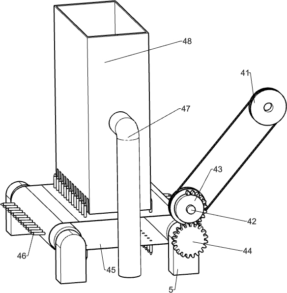
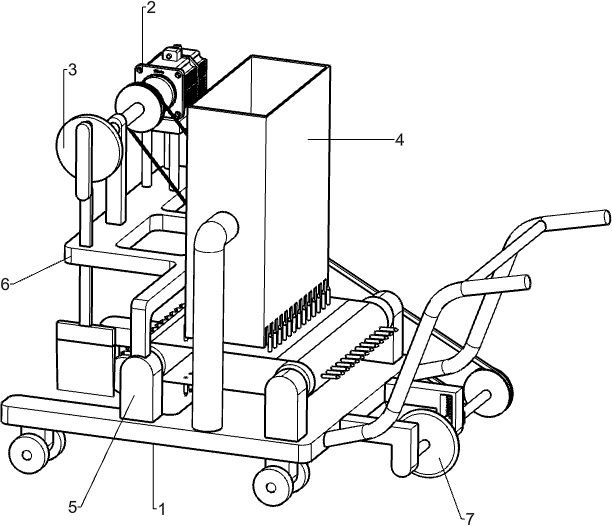
[0040] A desert sand-fixing device for environmental protection, such as figure 1 As shown, include cart 1, motor 2, grass plugging mechanism 3, grass lowering mechanism 4, fixed block 5, mounting frame 6 and slotting mechanism 7, both sides of front and back of cart 1 top are all left and right symmetrically provided with fixed block 5, Mounting frame 6 is connected between the tops of the two fixed blocks 5 on the left side, motor 2 is installed on the rear side of the mounting frame 6 tops, and a plugging mechanism 3 is connected between the output shaft of the motor 2 and the front side of the mounting frame 6 tops , between the grass plugging mechanism 3 and the fixed block 5, the grass-lowering mechanism 4 is connected, and the right side of the cart 1 is connected with the grass-lowering mechanism 4 with a slotting mechanism 7.

[0041] When it is necessary to fix sand in the desert, the user first places the straw in the grass-lowering mechanism 4, then starts the moto...

Embodiment 2

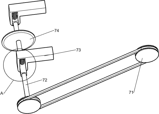
[0043] On the basis of Example 1, such as figure 2 As shown, the grass plugging mechanism 3 includes a first rotating shaft 31, a bearing seat 32, a disc 33, a first rotating column 34 and a grass plugging rod 35, and the front side of the mounting bracket 6 top is provided with a bearing seat 32, and the bearing seat 32 top rotates is connected with the first rotating shaft 31, the rear side of the first rotating shaft 31 is connected with the output shaft of the motor 2, the front side of the first rotating shaft 31 is provided with a disc 33, and the eccentric position of the front side of the disc 33 is rotationally connected with the first rotating shaft Post 34, mounting frame 6 front sides are slidingly connected with plug grass bar 35, and plug grass bar 35 tops are connected with the rotation type of first rotating post 34 bottoms.

[0044] When the motor 2 starts, the motor 2 rotates through the first rotating shaft 31 to drive the lower groove mechanism to rotate, ...


PUM


Abstract

The invention relates to the field of desert greening, in particular to a desert sand fixation device for environmental protection. According to the desert sand fixation device for environmental protection, time and labor are saved, and the working efficiency is high. According to the technical scheme, the desert sand fixation device for environmental protection comprises a cart, installation frames, a motor and a straw feeding mechanism, wherein fixing blocks are correspondingly arranged around the bottom of the cart; the installation frames are connected between the top ends of every two fixing blocks on the same side; the motor is installed on the installation frame on the side away from the fixing blocks; and the straw feeding mechanism is connected between an output shaft of the motorand the installation frame on the side away from the motor. According to the desert sand fixation device, through the mutual matching between a first rotating shaft, a bearing seat, a disc and otherparts, a straw feeding rod moves up and down and simultaneously moves to the right to continuously feed the straw into a groove, so as to achieve the effect of sand fixation in the desert.

Description

technical field [0001] The invention relates to the field of desert greening, in particular to a desert sand-fixing device for environmental protection. Background technique [0002] There are large deserts all over the world, and they are still expanding rapidly. The frequency of sandstorms is getting higher and higher, and the damage caused is also increasing. However, on the whole, the speed of governance has not kept up with the speed of desertification, and the trend of local improvement and overall deterioration is still continuing, and the situation of sand ingress and human retreat has not been fundamentally contained. For desert fixation and greening, the traditional solution is to use a single method for sand fixation. Usually, it is artificially placed on the trough where the straw has been laid, and the straw is plugged by hand, and then stepped on hard with the foot, so as to drive the straw into the trough. Internally, there are many shortcomings in such sand ...

Claims


Application Information

Patent Timeline
IPC IPC(8): E02D3/00
CPCE02D3/00
Inventor 黄何宝
Owner 黄何宝
Why Eureka
Eureka Blog
Learn More